Electronic part compression bonding apparatus and method

a technology of electronic parts and compression bonding, which is applied in the direction of non-electric welding apparatus, welding apparatus, manufacturing tools, etc., can solve the problems of difficult to satisfactorily adjust the amount of elongation, poor connection of electronic parts and glass substrates, etc., and achieve accurate control

Inactive Publication Date: 2006-07-11
SHIBAURA MECHATRONICS CORP
View PDF24 Cites 27 Cited by
  • Summary
  • Abstract
  • Description
  • Claims
  • Application Information

AI Technical Summary

Benefits of technology

[0022]Specifically, the pressure control unit and the heating unit are controlled based on the thermocompression bonding condition data in which at least one of the pressure and heating temperature is variably set during the process from start until completion of the thermocompression bonding operation of the electronic parts. In the thermocompression bonding condition data,

Problems solved by technology

Therefore, it has been difficult to satisfactorily adjust the amounts of elongation which occurs during the thermocompression bonding, with respect to various types of the electronic parts 2.
When the actual amount of

Method used


Image

  • Electronic part compression bonding apparatus and method
  • Electronic part compression bonding apparatus and method
  • Electronic part compression bonding apparatus and method

Examples


Embodiment Construction

[0041]An embodiment of the electronic part compression bonding apparatus and the electronic part compression bonding method according to the present invention is detailed hereinbelow with reference to FIGS. 4 to 17.

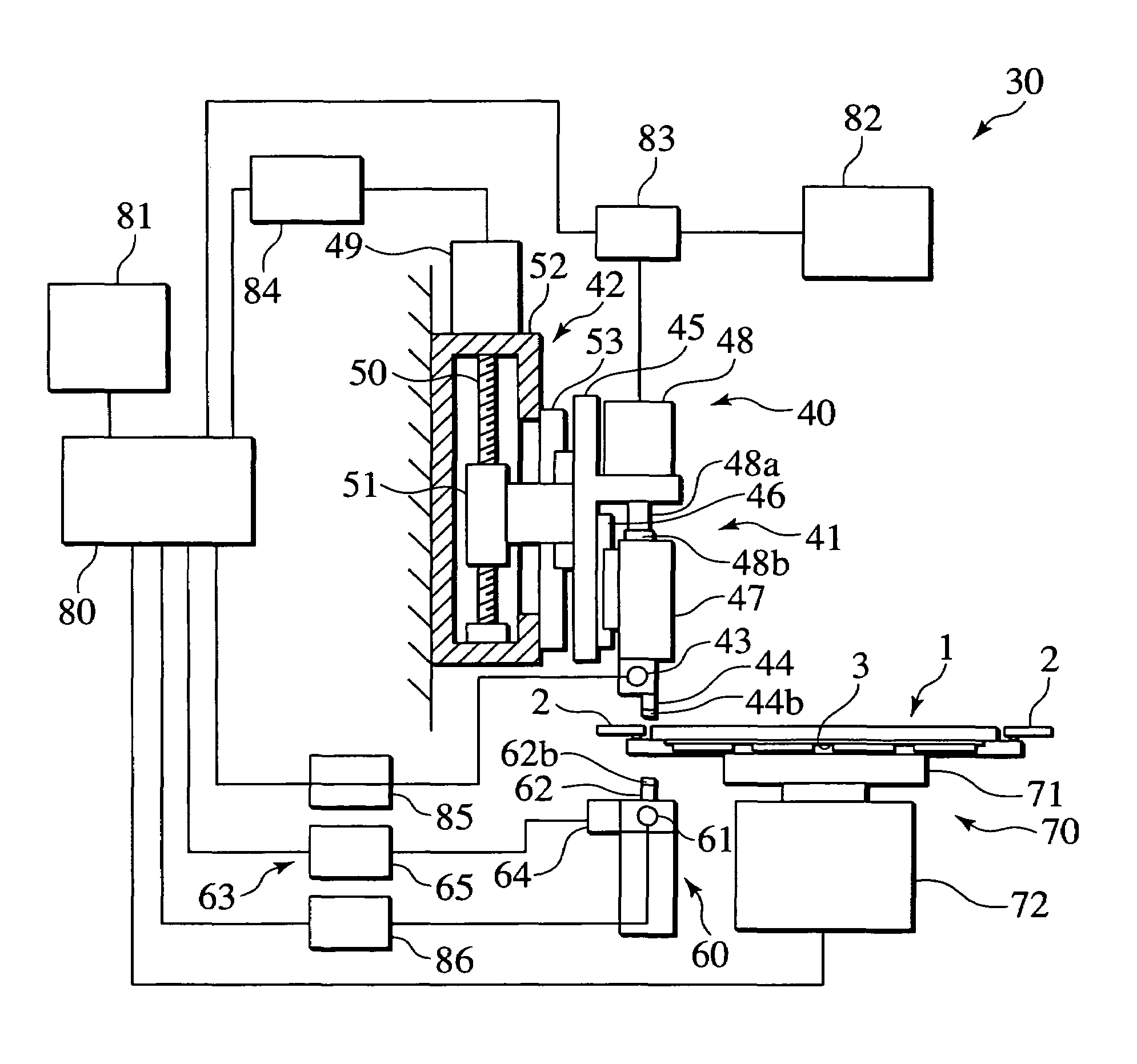
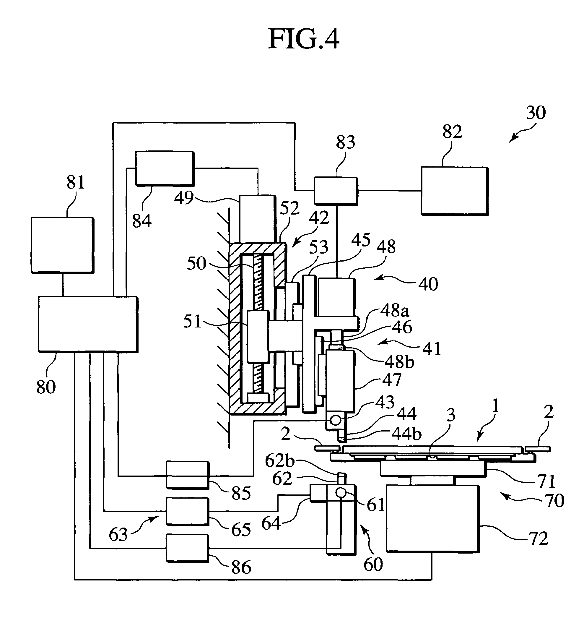
[0042]FIG. 4 is a cross-sectional side view partially showing an example of a construction of the electronic part compression bonding apparatus according to the embodiment of the present invention. Note that, in FIG. 4, the same components as those in the conventional apparatus are denoted with the same reference numerals to omit description thereof.

[0043]In FIG. 4, the electronic part compression bonding apparatus 30 according to the embodiment of the present invention includes a compression bonding head unit 40, a pressure receiving unit 60 placed to face the compression bonding head unit 40, a substrate stage 70, and a control device 80.

[0044]The compression bonding head unit 40 is provided with a head section 41, a lifting device 42 which raises and lowers the head se...


PUM

PropertyMeasurementUnit
Temperatureaaaaaaaaaa
Pressureaaaaaaaaaa

Abstract

An electronic part compression bonding apparatus includes a compression bonding unit which bonds the electronic parts onto the substrate by thermocompression, a pressure supply unit, a pressure control unit which controls pressure, a heating unit which heats the compression bonding unit, a temperature control unit, and a thermocompression bonding control unit which controls the pressure control unit and the heating unit based on thermocompression bonding condition data in which at least one of pressure and heating temperature is variably set during a process from start until completion of a thermocompression bonding operation of the electronic parts. In the thermocompression bonding condition data, the pressure is set to a first pressure in a first stage in a process of the thermocompression bonding operation and a second pressure, which is lower than the first pressure, in a second stage that follows the first stage.

Description

TECHNICAL FIELD[0001]The present invention relates to an electronic part compression bonding apparatus and an electronic part compression bonding method, by which electronic parts are bonded onto a substrate by compression. The present invention relates particularly to a technology which prevents poor connection of the electronic parts to the substrate by accurately controlling an elongation amount of the electronic parts to be bonded onto the substrate by thermocompression.BACKGROUND ART[0002]Conventionally, an electronic part compression bonding apparatus has been known which mounts electronic parts, each formed by a film-shaped member, onto a substrate made of glass or the like. This apparatus has been known as an electronic part compression bonding apparatus for manufacturing a flat panel display typified by a plasma display panel (PDP).[0003]FIG. 1 is a plan view showing an example of a glass substrate on which electronic parts are mounted by an electronic part compression bond...

Claims


Application Information

Patent Timeline
IPC IPC(8): H01L21/603H01L21/60B23K20/02
CPCB23K20/023B23K2201/42B23K2201/40B23K2101/40B23K2101/42H01L21/60
Inventor OGIMOTO, SHINICHIMORITA, KOJI
Owner SHIBAURA MECHATRONICS CORP
Why Eureka
Try Eureka