Method for correcting errors by de-embedding dispersion parameters network analyst and switching module

a technology of dispersion parameters and network analysts, applied in the direction of electronic circuit testing, measurement devices, instruments, etc., can solve the problems of time-consuming and complex calibration, error interferences throughout the network analyzer itself, and falsification of measurement results, etc., to achieve less loss of time, less expensive, and rapid conversion of multi-port solutions

Inactive Publication Date: 2006-07-11
ROHDE & SCHWARZ GMBH & CO KG
View PDF7 Cites 18 Cited by
  • Summary
  • Abstract
  • Description
  • Claims
  • Application Information

AI Technical Summary

Benefits of technology

[0024]Being based on the invented procedure and the invented network analyzer, that is to say, the circuit module, it is possible, from the now available 2-port-solution to very rapidly convert complex multiport solutions for the network analyzer. This requires far less loss of time than the known multiport procedure. The invented procedure presents, in this way, a De-embedding, Multiport Procedure (hereinafter, “DMV”), which essentially is less expensive than the known multiport calibration procedure based on a few calibrations. Very importantly, the invention permits applications on network analyzers, which have 3 or 4 measurement positions and wherein a switching matrix is connected to the gates, which are not possible with the known multiport calibration procedure.
[0025]A particular advantage of the proposed procedure lies in the simple possibilities of implementation in a network analyzer. Further, the procedure has superiorities over the known multiport-calibration method, in that not all signal paths need be measured, if only one or a few scattering parameters are being sought. For a comprehensive error correction of a scattering matrix of a device under test, however, all k possible signal paths between two ports must be measured and therefrom the reflection parameters of combined ports in the active state are determined.
[0029]In a preferred embodiment of the invented procedure, for the determination of the reflection factors of 2-port in the inactive state, the through connections are maintained as in the case of the established 2-port calibration in accord with a known procedure, so that no additional connection effort is necessary. However, as compared to a basic 2-port, 7-term method, a reduced connection expense is gained. Moreover, the already established results obtained from the said through connection calibrations of the 2-ports in the active state can be used. Depending on the network analyzer, for each reflection parameter to be determined of a port a further 2-port measurement with respectively a switched off port must be carried out in the inactive state. However, essentially, much more time consuming than the measurements themselves is the making of new connections. The invented procedure also permits the de-embedding step with the inclusion of carrying out the implementation of the well known 2-port error correction procedure in each network analyzer.
[0061]In claim 9, in an extended manner, is proposed an advantageous possibility for the treatment of the device under test with differential and common mode at the contact terminals. In accord with this, the device under test is described, instead of by the customary scattering parameters for an unsymmetrical mode, with scattering parameters for the common and differential modes. The procedure distinguishes itself above the method used up to now with the ideal transformer, in that all dissipation mechanisms have an under-support as individual, physically recoverable quantities, thus clearly providing more information to the developers allowing them to improve their product in its electrical characteristics. With this embodiment of the invented procedure, devices such as SAW filter and balance devices (baluns) can be analyzed simply, quickly and in great detail.

Problems solved by technology

In any case, error interferences occur throughout the network analyzer itself, such as, for example, improper interlinkage or mismatching, which falsify the results of measurements.
However, a calibration is often time consuming and complex, and in many cases the exactness of a de-embedding step is sufficient.
These 1-port and 2-port calibration procedures form, however, no fully sufficient basis for error correction in the measurement of multiport objects.
One problem with multiport measurement is found therein, in that, namely all ports of the device under test are interlinked.
The calibration procedures presented in the said documentation for the error module for n-port network analyzers are direct multiport calibration procedures, which, to be sure, are exact, but however, with which, in practice, the necessary measurements and corrections are very time consuming.
The result of this is, that these procedures cannot be employed for network analyzers, which exhibit three or four measurement positions, which by means of two inner ports and a circuit matrix are connected with the ports of the device under test.

Method used


Image

  • Method for correcting errors by de-embedding dispersion parameters network analyst and switching module
  • Method for correcting errors by de-embedding dispersion parameters network analyst and switching module
  • Method for correcting errors by de-embedding dispersion parameters network analyst and switching module

Examples


Embodiment Construction

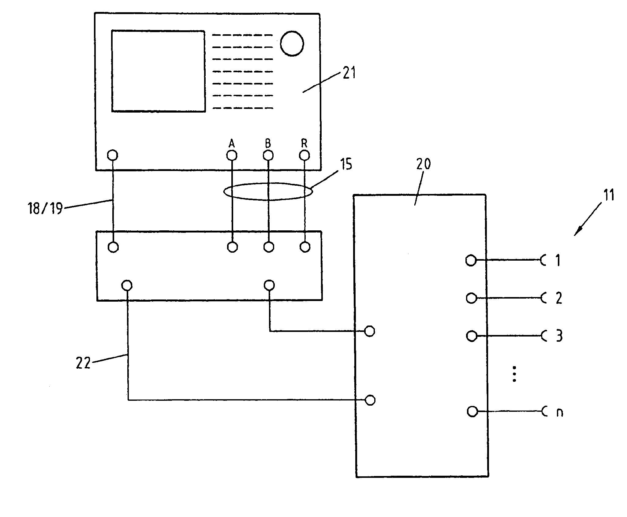
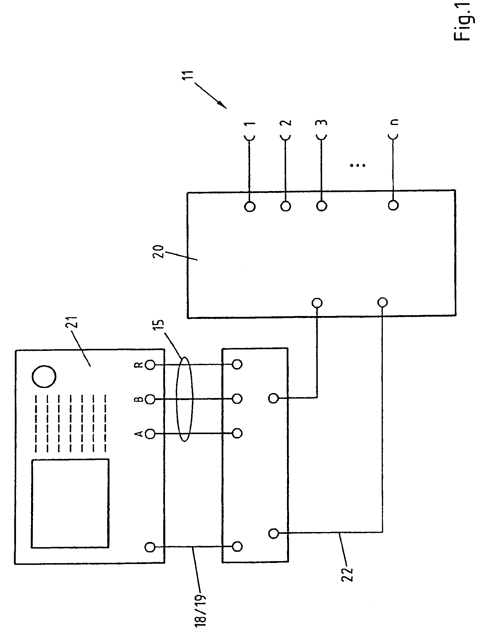
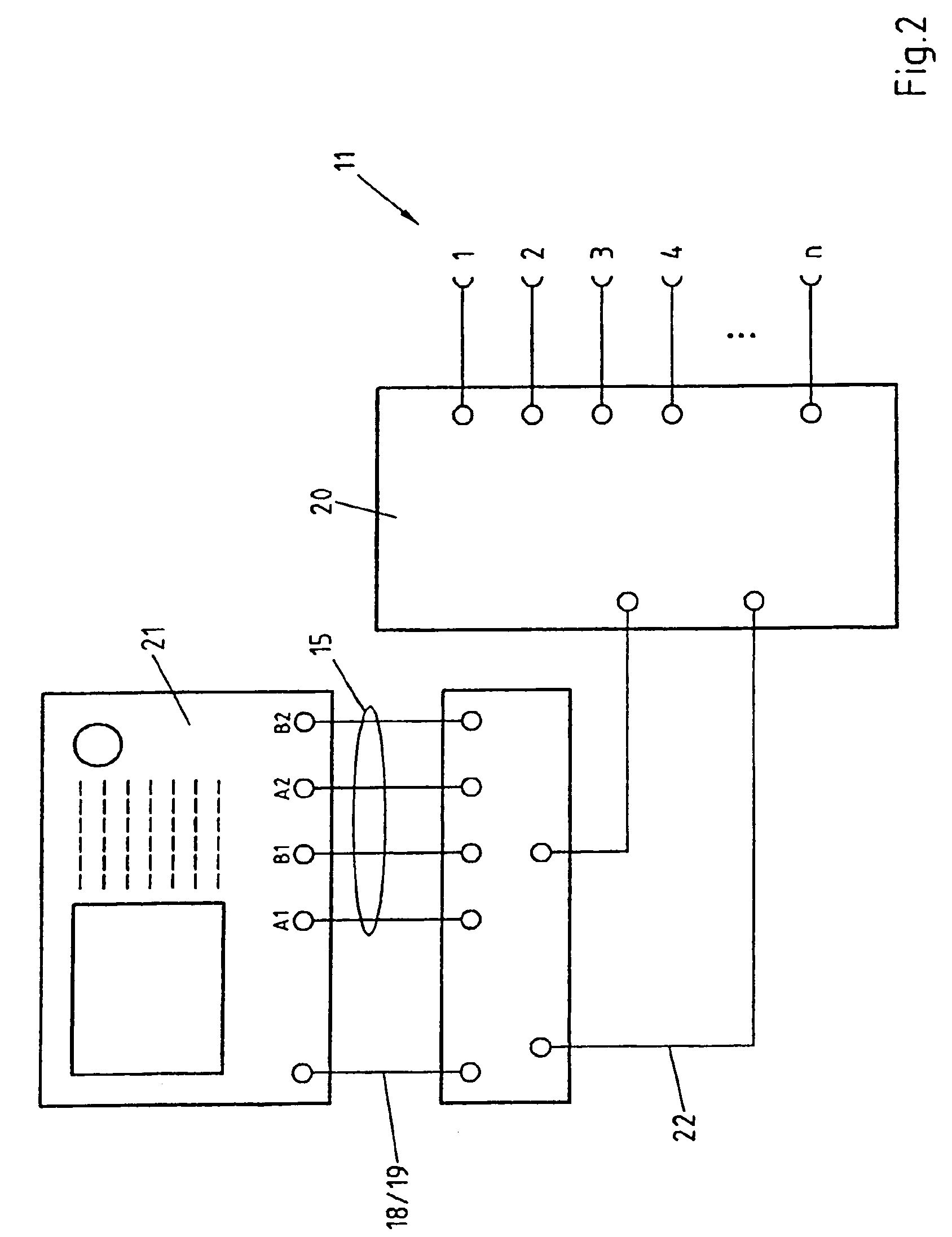
[0072]First, embodiment examples of a network analyzer is described with the aid of FIGS. 1–5, which show an arrangement wherein the invented de-embedding procedure may be applied.

[0073]FIG. 1 presents a network analyzer with three measurement positions 15, two inner ports 22 and n outer ports 11. A service and operating unit 21 is connected to two inner ports 22 of the network analyzer by three measurement positions, namely A, B and R as well as by high frequency lines 18, 19. The two inner ports 22 are, on their own part, connected through a switching module 20 with n outer ports 11. Two of the measurement positions A and B capture back-running signals from the outer ports 11 and one of the measurement positions, i.e., R, picks up the signals directed to the outer ports 11. The high frequency supply lines 18, 19 are used to conduct incoming signals to the outer ports 11, whereby also a (not shown) reflectometer also guides the respective signal to the measurement position R for th...


PUM


Abstract

The invention relates to a method for correcting errors by de-embedding scattering parameters of a device under test associated with measuring ports (11), the parameters being measured by a vector network analyzer including n measuring ports. The aim of the invention is to create a universal, precise and fast method of correcting errors of scattering parameters. To this end, the method includes the following steps: formula (1) two-port calibrations are carried out on different calibrating standards in any order in the active state between the measuring ports (11), as a basis for a first error correction; the reflection parameters of at least one part of the n measuring ports (11) are determined in the inactive state, by way of the results of two-port measurements carried out on at least one calibrating standard switched in the active and / or inactive state on measuring ports (11), as a basis for a second error correction. The invention also relates to a network analyzer and to a switching module for a network analyzer.

Description

BACKGROUND OF THE INVENTION[0001]The invention concerns a procedure for error correction by the de-embedding of a scattering parameter, which has been measured with an n-port containing, vectorial network analyzer, wherein the scattering parameter relates to a device under test connected to the said ports. The invention also concerns a vectorial network analyzer for the said procedure as well as a circuit module for the said network analyzer.[0002]In high frequency technology, the behavior of circuits is normally described in terms of scattering parameters. The scattering parameters represent complex reflection and transmission parameters of a circuit and join ingoing and outgoing waves with one another. A representation of this type where complex reflection and transmission parameters are concerned is especially well suited to the physical realities of the problems brought forth in high frequency technology.[0003]Thus, for example, a circuit, which is formed by a linear 2-port, and...

Claims


Application Information

Patent Timeline
Patent Type & Authority Patents(United States)
IPC IPC(8): G01R15/00G01R35/00
CPCG01R35/005
Inventor FABRY, HANS-JOACHIMHEUERMANN, HOLGER
Owner ROHDE & SCHWARZ GMBH & CO KG
Why Eureka
Try Eureka