Wireless communication apparatus and method

a technology of wireless communication and wires, applied in the direction of instruments, data switching networks, electric signalling details, etc., can solve the problems of limitative application range of wireless communication and wiring lines, and achieve the effects of reducing the cost per fine functional element, reducing the cost of commercial products, and reducing the size of wires

Active Publication Date: 2006-07-11
CANON KK
View PDF11 Cites 79 Cited by
  • Summary
  • Abstract
  • Description
  • Claims
  • Application Information

AI Technical Summary

Benefits of technology

[0013]The fine functional element of the invention becomes significant if three points are satisfied: the element should be fine; the element should have a communication function; and a plurality of fine functional elements as a whole provide one or more functions. A cost of a commercial product is important. The fine functional element of the invention is formed on a single substrate so that the cost per fine functional element can be reduced and the size thereof can be made small.

Problems solved by technology

Although wireless communications are essential for daily life, the application range of wireless communications is limitative.
These wiring lines pose a significant problem when one object is imaged at different angles or a display for a portable apparatus is used which is thin as a piece of paper and is used by being curved or bent.

Method used


Image

  • Wireless communication apparatus and method
  • Wireless communication apparatus and method
  • Wireless communication apparatus and method

Examples


first embodiment

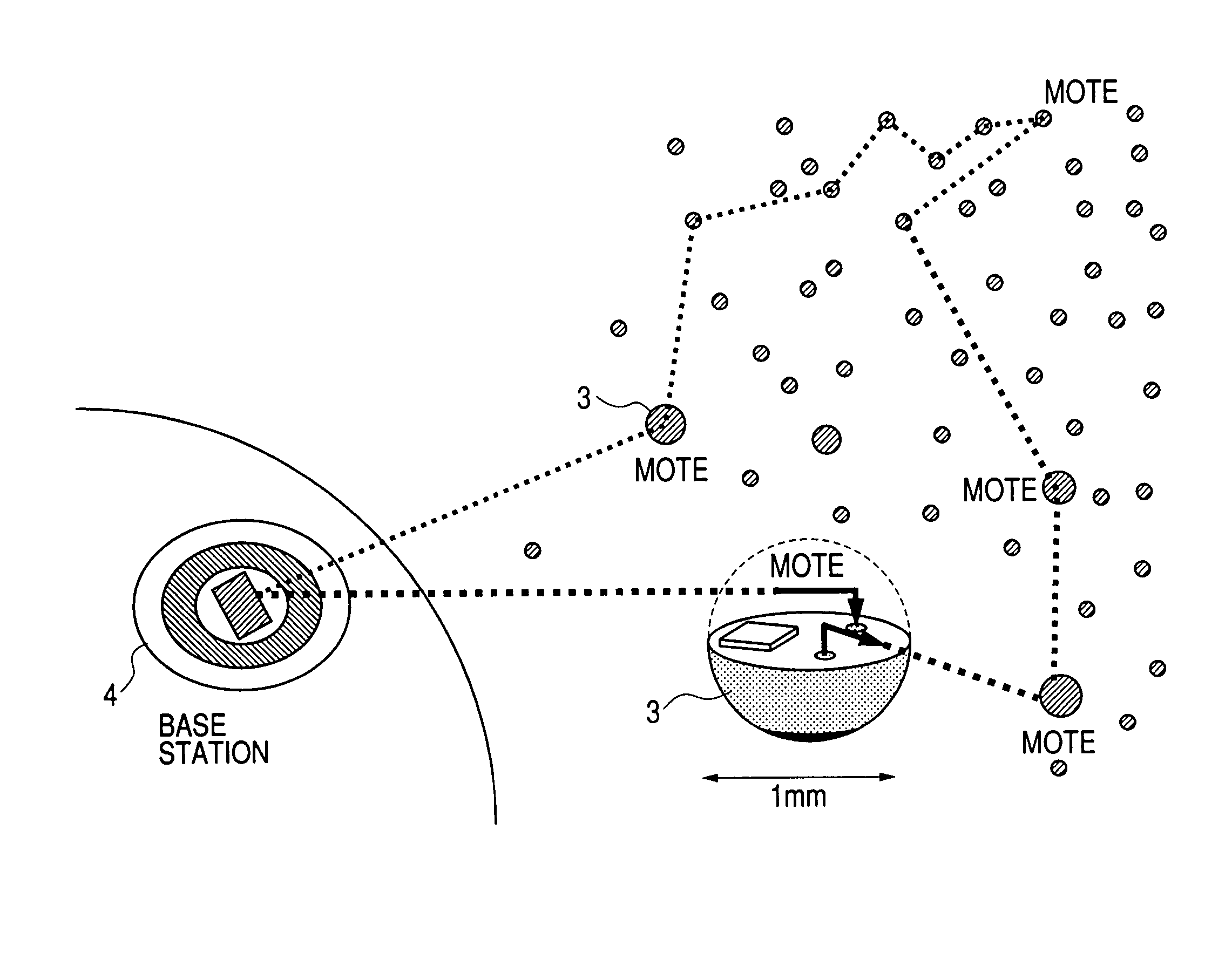
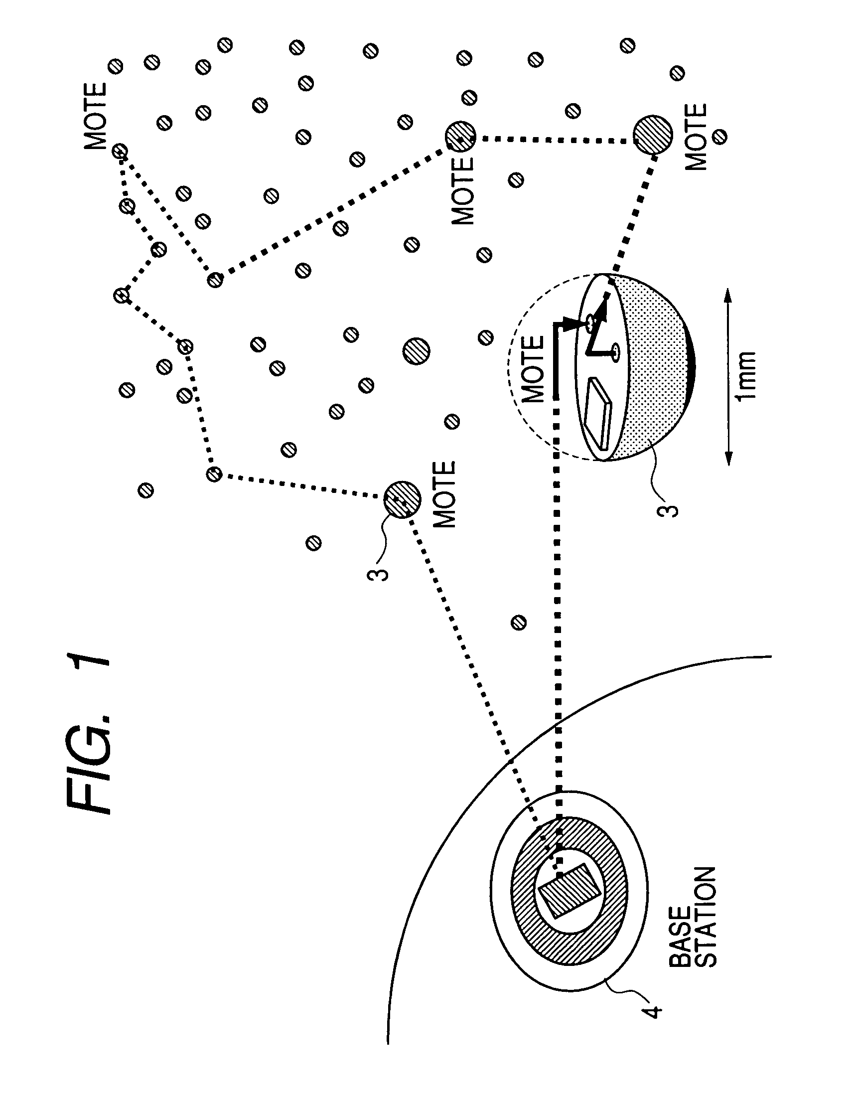
[0069]FIG. 1 is a conceptual diagram showing a wireless communication system according the invention. A number of fine micro functional elements (Motes) 3 each having a communication function are distributed here and there like stars in the cosmic Galaxy. Each Mote 3 has a wireless communication function using light or RF waves and communicates with a base station 4.

[0070]In the example shown in FIG. 1, the base station 4 communicates with Mote 3 near to the base station. This Mote 3 communicates with another Mote 3 near to the Mote 3. In this manner, communications are possible between each Mote 3 and base station 4. As shown in FIG. 1, each Mote 3 has a small outer shape, for example, a sphere having a diameter of 1 mm. Motes 3 and base station 4 constitute a wireless communication network. Each Mote 3 has, for example, a sensing function and is constitutes a sensing network.

[0071]Each Mote 3 has a sensing function for observing the environment of Mote 3, such as light, temperatur...

second embodiment

[0083]With reference to the accompanying drawings, description will be made on a wireless communication system with a wireless communication function according to a second embodiment of the invention.

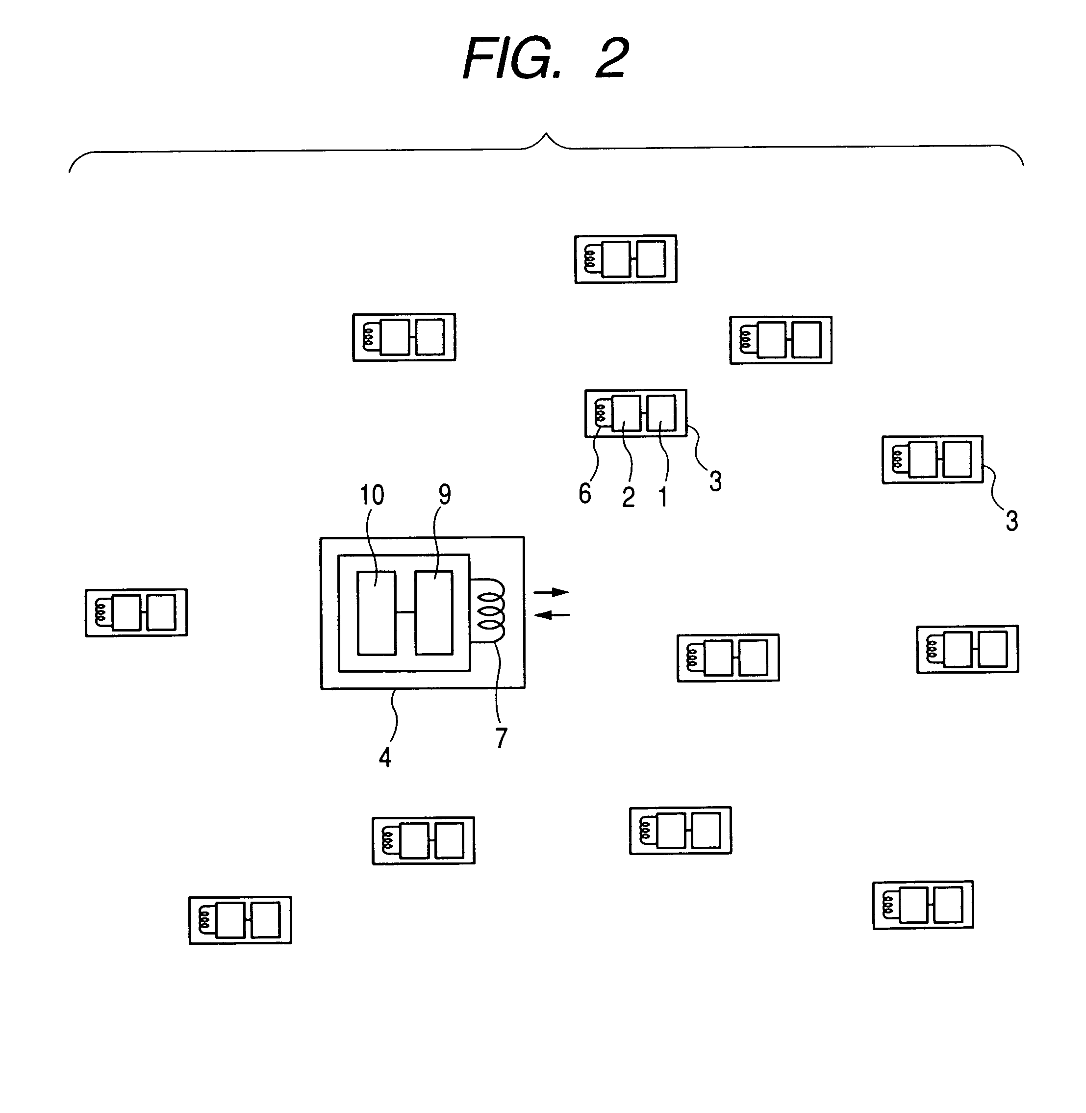
[0084]FIGS. 5 and 6 show the structure of a wireless communication system according to the second embodiment of the invention. Referring to FIG. 5, Motes 3 are disposed on the same substrate 5 in a matrix shape, each Mote being constituted of a functional element 1, a wireless communication element 2 and an antenna 6. A wireless communication unit 4 is formed on a substrate different from the substrate 5 and placed at a position spatially remote from the substrate 5, the wireless communication unit 4 a being constituted of an antenna 7 and a transmitter circuit 910. The wireless communication unit 4 has the function same as that of the base station 4 of the first embodiment. This system of the second embodiment is called a wireless array.

[0085]In this embodiment, electrical wiring lines...

third embodiment

[0092]In this embodiment, a procedure for data transmission / reception to be executed by a wireless communication system of the invention will be described with reference to the accompanying drawings.

[0093]FIGS. 9 to 11 illustrate a communication procedure between Mote 3 and the base station 4 according to the invention, the communication procedure including three types.

[0094]With the first communication procedure, as shown in FIG. 9, after a control signal is supplied from the base station, each Mote 3 provides a function. For example, this procedure is applicable to a display device. Namely, the base station 4 sends a display-on signal to each functional element 1 (in this example, a displaying element) disposed in a matrix shape. An image of text can therefore be displayed on a whole screen. In this case, after the base station 4 sends a control signal to each Mote 3, each Mote 3 provides its function without a necessity of sending a signal from the Mote 3 to the base station 4.

[0...


PUM


Abstract

A wireless communication apparatus and method is provided which makes discrete functional elements perform a cooperative work without various limitations caused by a wired configuration. The wireless communication apparatus has a plurality of fine functional elements 3 each having a communication unit for data transmission and reception by using radio waves or light and one or more unit other than the communication unit, and a base station 4 for controlling and collectively managing the fine functional elements through communications with the fine functional elements, wherein one or more units other than the communication unit are activated through communications of one of the fine functional elements 3 received control information from the base station 4 with another of the fine functional elements 3 via the communication units, to thereby make the discrete functional elements 3 perform a cooperative work.

Description

BACKGROUND OF THE INVENTION[0001]1. Field of the Invention[0002]The present invention relates to a wireless communication apparatus and method and a driving method for the wireless communication apparatus. More particularly, the present invention relates to a wireless communication apparatus having fine functional elements for communication by utilizing radio waves or light, and to a wireless communication method.[0003]2. Description of the Related Art[0004]Wireless communications utilizing radio frequency (RF) waves or light are recently prevailing. For example, a portable phone is a requisite wireless mobile communication tool capable of communications at any time and at any location using electromagnetic waves of a 900 to 1900 MHz band for example. Wireless communications utilizing radio frequency waves in the 2.45 GHz band are used as a communication means between personal computers or between a personal computer and a printer, in offices or homes, based upon the specifications ...

Claims


Application Information

Patent Timeline
Patent Type & Authority Patents(United States)
IPC IPC(8): G08C17/00G08B21/00G08C19/12H04B5/00H04Q7/20H04B7/00H04L12/28H04L12/56H04W84/18H04W88/02
CPCH04W88/02H04W84/18
Inventor NISHIMURA, NAOKISAITOH, KENJIIMAIZUMI, MASAAKISHIBATA, MASAAKI
Owner CANON KK
Why Eureka
Try Eureka