Disk drive with a dual-stage actuator and failure detection and recovery system for the secondary actuator

a secondary actuator and disk drive technology, applied in the field of magnetic recording hard disk drives, can solve the problems of vcm b>110/b> becoming unstable, reducing performance, and data loss of the disk driv

Inactive Publication Date: 2006-07-11
WESTERN DIGITAL TECH INC
View PDF17 Cites 25 Cited by
  • Summary
  • Abstract
  • Description
  • Claims
  • Application Information

AI Technical Summary

Problems solved by technology

In a dual-stage actuator disk drive as described above, failure of the secondary actuator will result in reduced performance and may lead to loss of data and / or failure of the disk drive.
However, if the microactuator 200 fails while the disk drive is under the control of dual-stage controller 410, then VCM 110 will become unstable.
However, because the low-frequency gain is still determined by the single-stage VCM controller, there is no improvement at low frequency.
However, increasing the low-frequency gain will also decrease the phase margin for the VCM controller, potentially to the point of instability of the VCM.
With the dual-stage controller having the characteristics represented by line 412 in FIG. 7, failure of the secondary actuator results in an unstable system.
This could lead to inoperability of the hard disk drive, or even failure with loss of data.
There are potential microactuator failure modes in which the motion is excessive, in which case the maximum gain value may be too high.
If the measured output was less than about 0.2 micrometer or more than about 1 micrometer during the static characteristics measurement, then this would likely indicate failure of the microactuator.
This type of microactuator also has a resonant frequency around 2 kHz, so if the maximum gain from the dynamic characteristics measurement is less than about 1 kHz or greater than about 3 kHz, then this would likely indicated failure of the microactuator.

Method used


Image

  • Disk drive with a dual-stage actuator and failure detection and recovery system for the secondary actuator
  • Disk drive with a dual-stage actuator and failure detection and recovery system for the secondary actuator
  • Disk drive with a dual-stage actuator and failure detection and recovery system for the secondary actuator

Examples


Embodiment Construction

Prior Art

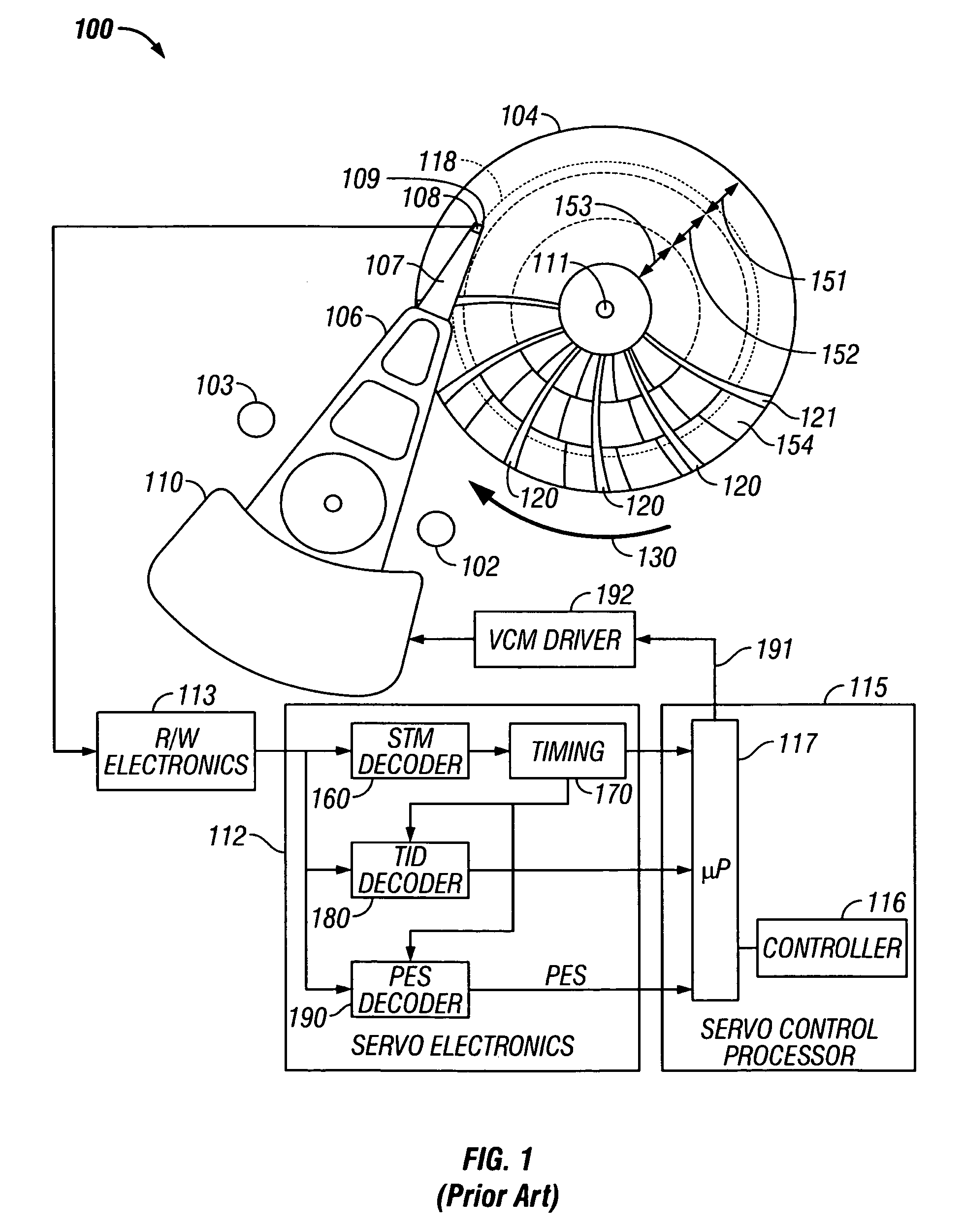
[0033]FIG. 1 is a block diagram of a conventional single-stage actuator disk drive that uses servo positioning information located in angularly-spaced servo sectors for positioning the read / write heads. The disk drive, designated generally as 100, includes data recording disk 104, a voice coil motor (VCM) 110 as the primary and only actuator, an inner-diameter (ID) crash stop 102 and an outer-diameter (OD) crash stop 103 for the VCM 110, an actuator arm 106, a suspension 107, a head carrier or air-bearing slider 108, a data recording transducer 109 (also called a head, recording head or read / write head), read / write electronics 113, servo electronics 112, and servo control processor 115.

[0034]The recording head 109 may be an inductive read / write head or a combination of an inductive write head with a magnetoresistive read head and is located on the trailing end of slider 108. Slider 108 is supported on the actuator arm 106 by a suspension 107 that enables the slider to “pitc...


PUM

PropertyMeasurementUnit
frequencyaaaaaaaaaa
frequencyaaaaaaaaaa
frequencyaaaaaaaaaa

Abstract

A dual-stage actuator disk drive has calibration tracks located in a nondata band, and uses a secondary-actuator failure detection and calibration test run by the servo control processor. The calibration tracks contain a pattern of pre-written magnetized test blocks. The test is run with the primary actuator biased against a crash stop, which enables the read head to access the calibration tracks. The servo control processor generates a test signal to the secondary actuator and receives a calibration signal from the read head as the read head detects the test blocks in the calibration tracks. The test comprises two measurements: a measurement of the secondary actuator static characteristics, and a measurement of the secondary actuator dynamic characteristics.

Description

BACKGROUND OF THE INVENTION[0001]1. Field of the Invention[0002]This invention relates generally to magnetic recording hard disk drives, and more particularly to a disk drive with a dual-stage actuator for positioning the read / write heads.[0003]2. Description of the Related Art[0004]Magnetic recording hard disk drives with dual-stage actuators for positioning the read / write heads on the disks have been proposed. A rotary voice-coil-motor (VCM) is typically the primary actuator, with the secondary actuator attached to the VCM and the read / write heads attached to the secondary actuator. A servo control system receives servo positioning information read by the read / write heads from the data tracks and generates control signals to the primary and secondary actuators to maintain the heads on track and move them to the desired tracks for reading and writing of data. As in conventional single-stage actuator disk drives, each read / write head is attached to the end of a head carrier or air-b...

Claims


Application Information

Patent Timeline
Patent Type & Authority Patents(United States)
IPC IPC(8): G11B5/596
CPCG11B5/5552G11B5/5534
Inventor WHITE, MATTHEW T.YAMAMOTO, SATOSHI
Owner WESTERN DIGITAL TECH INC
Why Eureka
Try Eureka