Digital data radio receiving device and method

a digital data and receiving device technology, applied in the direction of repeater circuits, polarisation/directional diversity, coding, etc., can solve the problems of difficult use of diversity reception technology and the restriction of arranging a plurality of antennas physically close to each other, so as to ensure the mobility of the transmitter, improve the transmission quality, and enhance the movable range of the transmitter

Inactive Publication Date: 2006-07-11
REDWOOD TECHNOLOGIES LLC
View PDF19 Cites 8 Cited by
  • Summary
  • Abstract
  • Description
  • Claims
  • Application Information

AI Technical Summary

Benefits of technology

[0006]It is an object of the present invention to provide a wireless receiver and wireless reception method which improves the transmission quality and can ensure the transmitter's mobility by enhancing a movable range of the transmitter for mobile transmission.

Problems solved by technology

However, the diversity reception requires selection and synthesis in the RF / IF region, causing a restriction of arranging a plurality of antennas physically close to each other.
Accordingly, the use of the diversity reception technology has been difficult when a plurality of receivers are arranged at different positions for ensuring the wireless camera's mobility.

Method used


Image

  • Digital data radio receiving device and method
  • Digital data radio receiving device and method
  • Digital data radio receiving device and method

Examples


Embodiment Construction

[0018]As an embodiment of the present invention, the following describes a ground digital wireless relay system (hereafter referred to simply as the wireless relay system) used to photograph a relaying scene for televising news programs, sports programs, various event programs, etc.

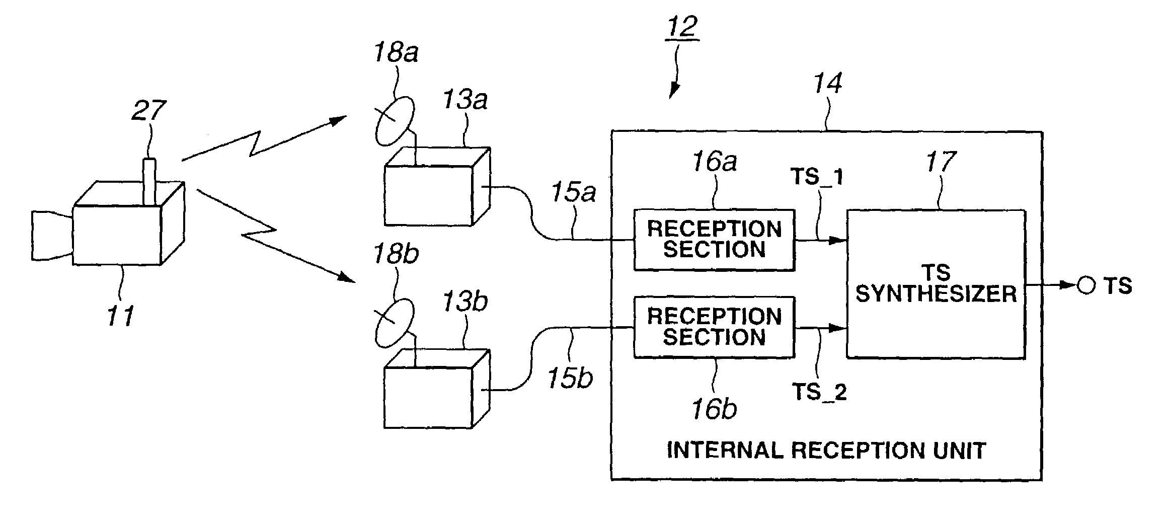
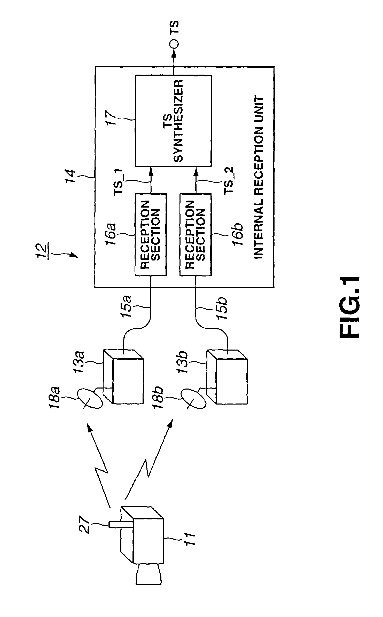
[0019]FIG. 1 shows a configuration diagram of the wireless relay system according to the embodiment of the present invention.

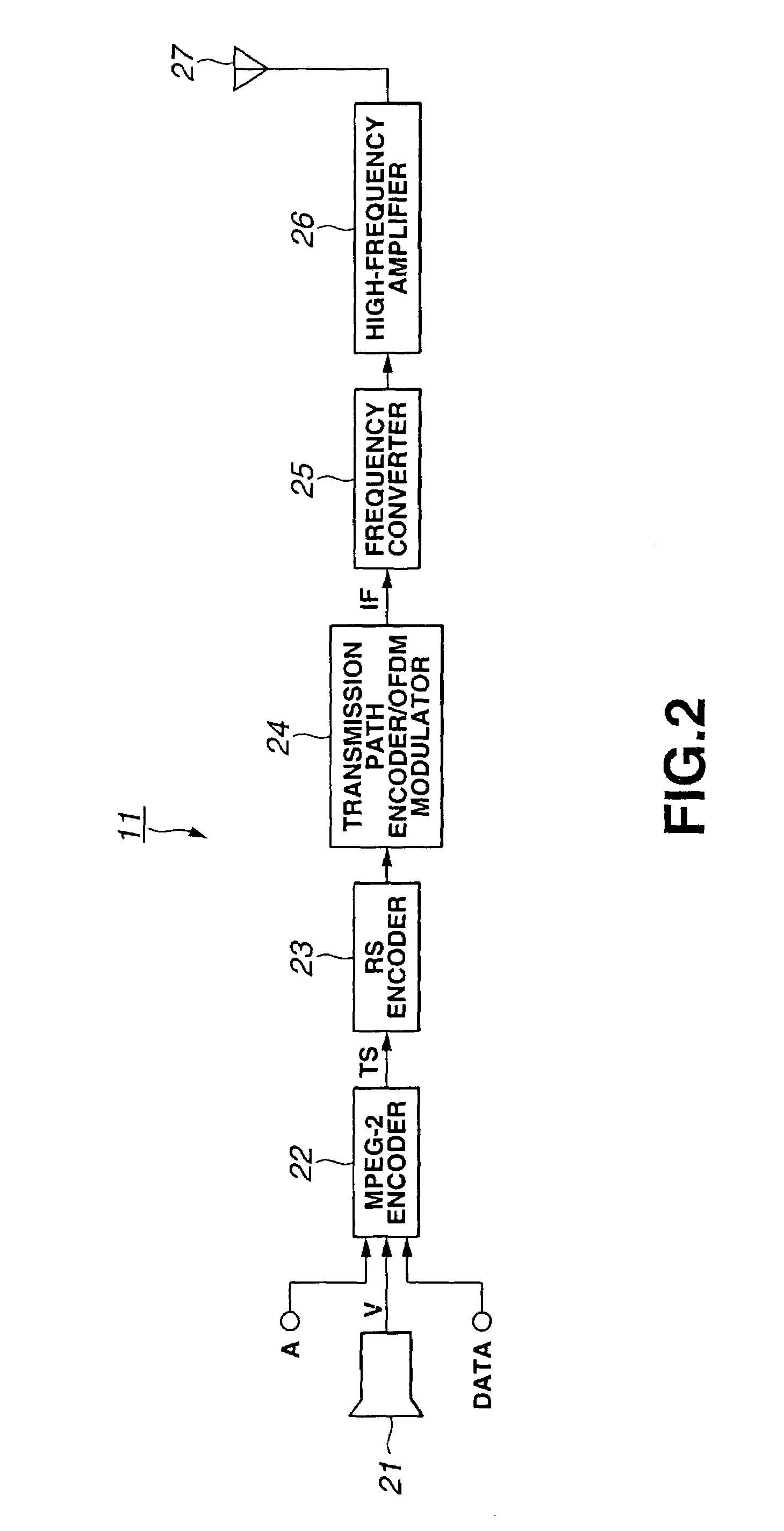
[0020]As shown in FIG. 1, a wireless relay system comprises a wireless camera 11 for photographing a subject and a reception relay station 12 for receiving a signal transmitted from the wireless camera 11.

[0021]The wireless relay system 1 is used to photograph a relaying scene for televising news programs, sports programs, various event programs, etc. Using the ground wave, the system transmits wirelessly a video signal etc. for a material video taken by the wireless camera 11 to the reception relay station 12. Since no cable is needed between the camera and the relay station, the w...


PUM


Abstract

A wireless relay system (1) comprises a wireless camera (11) and a reception relay station (12). The reception relay station (12) comprises a plurality of external reception units (13) arranged at spatially different positions and an internal reception unit (14). Each reception section (16) in the internal reception unit (14) demodulates a signal received in the external reception unit (13) and outputs a transport stream. At this time, each reception section (16) sets an error indicator flag to 1 for a TS packet causing a transmission error which exceeds the error correction capability. A TS synthesizer section (17) in the internal reception unit (14) completely synchronizes a plurality of input transport streams by referencing synchronization bytes, PID, and CC values, and selects to output a TS packet having the error indicator flag not set to 1.

Description

TECHNICAL FIELD[0001]The present invention relates to a wireless receiver and method for receiving a signal transmitted wirelessly from one transmitter and demodulating a digital data sequence.BACKGROUND ART[0002]Conventionally, a wireless camera is used to photograph a relaying scene for televising news programs, sports programs, various event programs, etc. This wireless camera generates a video or voice signal and transmits the signal to a base station such as a relay mobile by means of the ground wave radio communication. Compared to a cable-connected camera, the wireless camera saves labor of installing or removing cables and increases flexibility of camera angles and photographing positions. This improves mobility of the camera at the scene.[0003]Further, in recent years, the wireless camera transmission system is increasingly using a digital modulation system which digitizes video or voice signals.[0004]It is important for a relay system using the digitized wireless camera to...

Claims


Application Information

Patent Timeline
Patent Type & Authority Patents(United States)
IPC IPC(8): H03M13/03H04B7/08H04B7/10H04J11/00H04L1/00H04L1/02H04L1/06H04N19/00H04N19/102H04N19/166H04N19/196H04N19/423H04N19/65H04N19/67H04N19/70H04N19/89
CPCH04B7/082H04L1/0045H04L1/06H04L1/0057H04L2001/0097H04L1/0082
Inventor IKEDA, YASUNARISHIROTA, NORIHISAMATSUMOTO, HIDEYUKI
Owner REDWOOD TECHNOLOGIES LLC
Why Eureka
Try Eureka