Adjustable system and method for supporting and joining structural members

a structural member and adjustment system technology, applied in the field of structural member joining, can solve the problems of time-consuming and laborious process, damage to parts, and impair the effectiveness of the joint and the finished wing, and achieve the effect of minimizing the factory space and time required

Inactive Publication Date: 2006-07-18
THE BOEING CO
View PDF14 Cites 30 Cited by
  • Summary
  • Abstract
  • Description
  • Claims
  • Application Information

AI Technical Summary

Benefits of technology

[0008]The present invention meets these and other needs by providing an apparatus and associated method for joining structural members, including large, heavy, and complex members formed of various materials. The apparatus includes a support structure of extendable members, each with an adjustable support surface for engaging the structural members so that structural members of different sizes and shapes can be accommodated. Gantries, which are longitudinally adjustable, support a joining device having co-operable heads that engage the structural members. The heads are adjustable in a transverse direction along the gantries so that the heads can be configured in an opposing configuration and used to join the structural members therebetween. The structural members can be arranged and joined on the same apparatus, thus minimizing the factory space and time required for assembly.

Problems solved by technology

For example, if the skins and / or stringers are not removed from the fixtures for cleaning after the holes are drilled, debris introduced between the members during drilling can damage the parts or impair the effectiveness of the joint and the finished wing.
Thus, the process is time-consuming and labor intensive.
Further, the fixtures, which must be shaped according to the particular members that are to be joined, add to the cost of manufacture.
Additionally, sufficient factory space is required for moving and processing the members, and special equipment may be required for moving the members if they are large, heavy, or subject to being damaged.
However, for members that are large, complex, or formed of certain materials, it can be difficult or impossible to predict the precise placement of the holes.
If the holes are formed during manufacture of the members, the corresponding holes of the different members may not properly align during assembly.

Method used


Image

  • Adjustable system and method for supporting and joining structural members
  • Adjustable system and method for supporting and joining structural members
  • Adjustable system and method for supporting and joining structural members

Examples


Embodiment Construction

[0026]The present invention now will be described more fully hereinafter with reference to the accompanying drawings, in which some, but not all embodiments of the invention are shown. Indeed, the invention may be embodied in many different forms and should not be construed as limited to the embodiments set forth herein; rather, these embodiments are provided so that this disclosure will satisfy applicable legal requirements. Like numbers refer to like elements throughout.

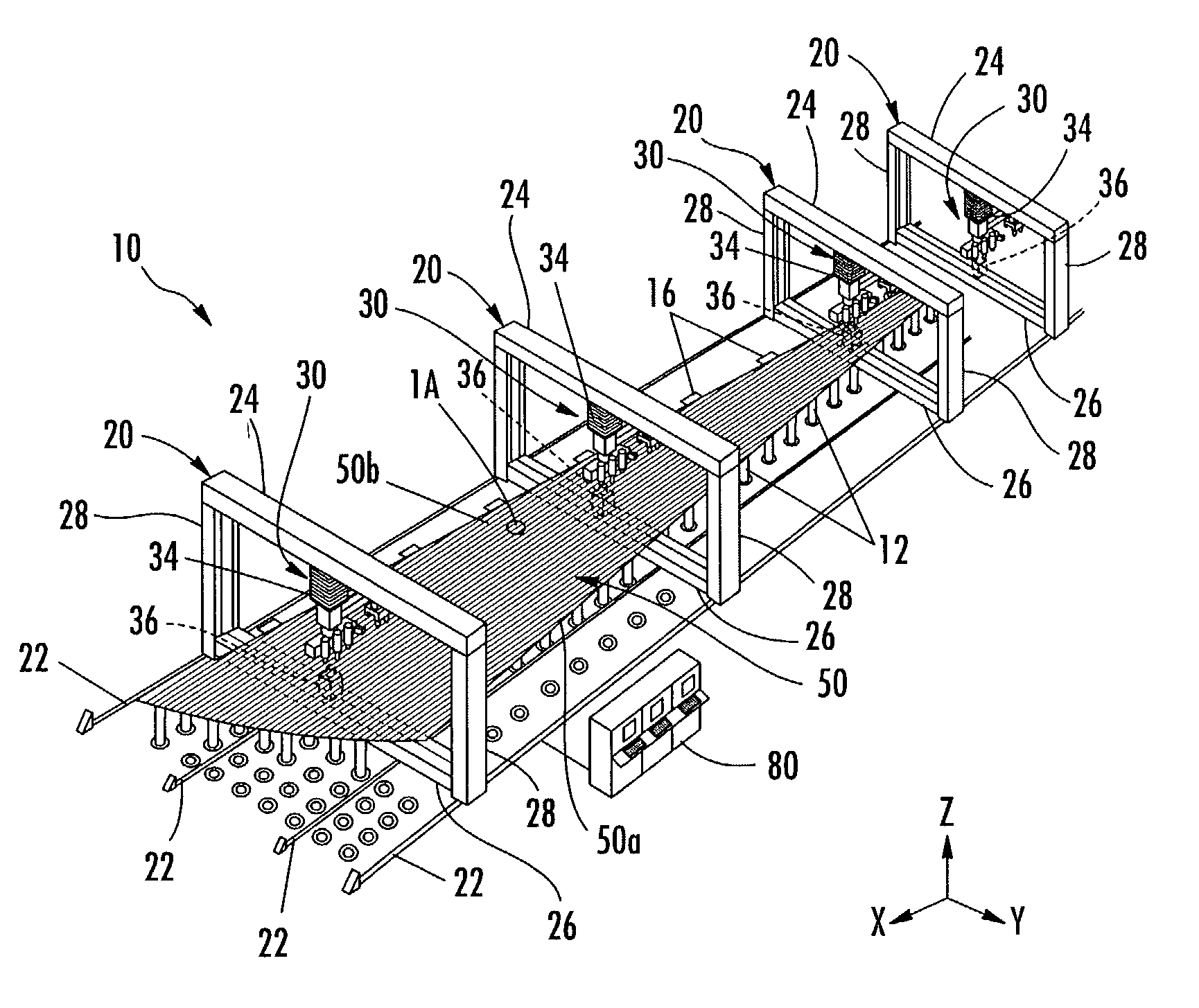
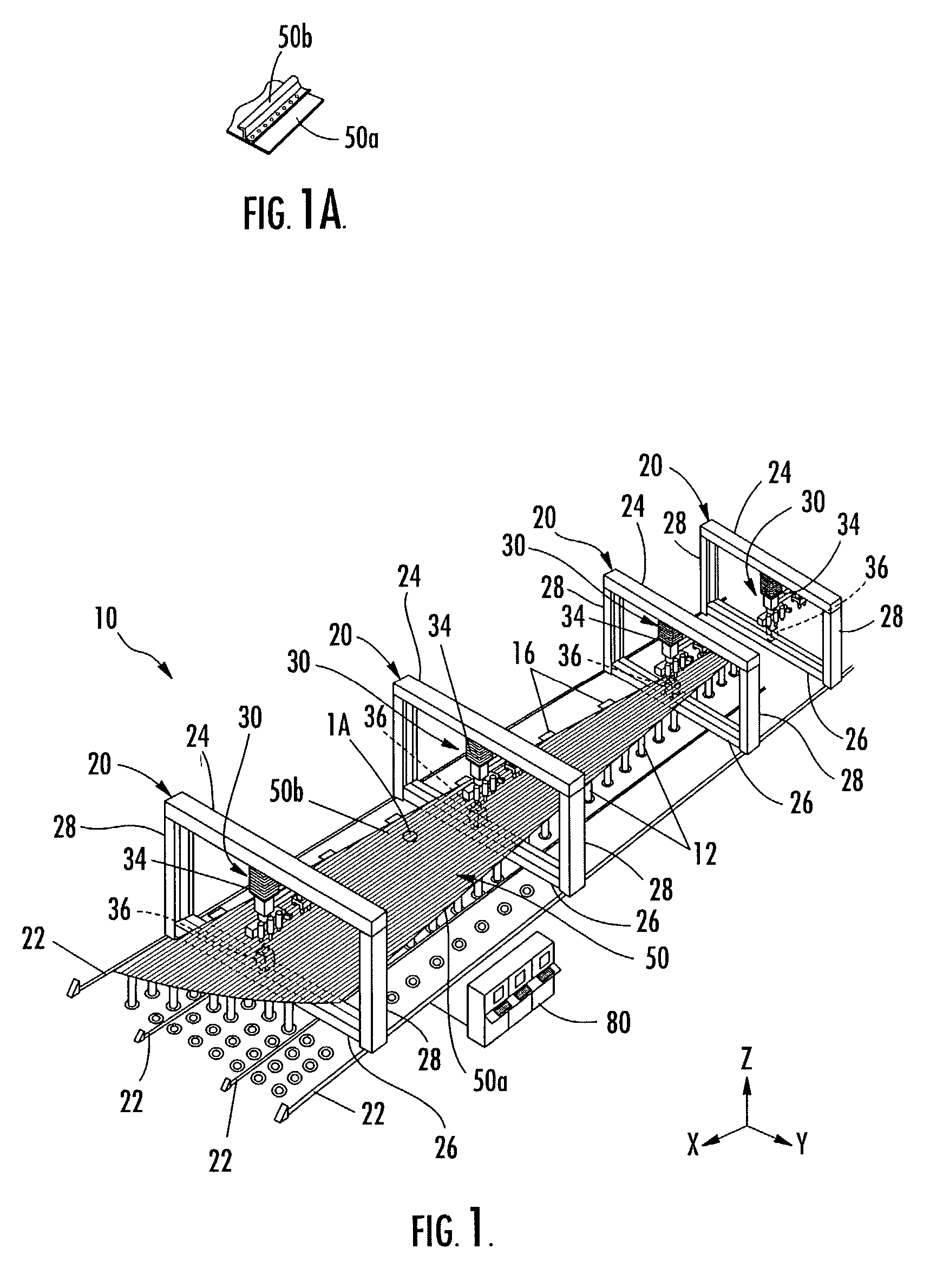
[0027]Referring now to the figures and, in particular, to FIG. 1, there is shown an apparatus 10 for joining structural members referred to collectively by the reference numeral 50, according to one embodiment of the present invention. The joining apparatus 10 can be used to join any number of structural members 50, and the structural members 50 can be formed of a variety of materials such as aluminum, titanium, steel, alloys, polymers, composites, and the like. According to one embodiment of the present invention,...


PUM

PropertyMeasurementUnit
friction forceaaaaaaaaaa
lengthaaaaaaaaaa
thermal expansionaaaaaaaaaa

Abstract

An apparatus and associated method for joining structural members are provided. The apparatus includes a support structure of extendable members, each with an adjustable support surface for engaging the structural members so that structural members of different sizes and shapes can be accommodated. Gantries, which are longitudinally adjustable, support a joining device having co-operable heads that engage the structural members. The heads are adjustable in a transverse direction along the gantries so that the heads can be configured in an opposing configuration and used to join the structural members therebetween.

Description

BACKGROUND OF THE INVENTION[0001]1) Field of the Invention[0002]The present invention relates to the joining of structural members and, more particularly, to a system and method for adjustably supporting and joining structural members using heads adjustably mounted on gantries.[0003]2) Description of Related Art[0004]Certain structural parts have conventionally been manufactured by joining a number of preformed structural members. For example, in the aircraft industry, wings are often manufactured by forming, and then joining, one or more skins and stringers. The skins, which are typically large and thin, form the outer contoured airfoil of the wing, and the stringers are joined to the skin to strengthen and stiffen the skins. According to one conventional manufacturing process, the skins and stringers are assembled in place in specially shaped fixtures and clamped therein with straps, which hold the skins and stringers in a desired configuration. Holes are then drilled through the ...

Claims


Application Information

Patent Timeline
Patent Type & Authority Patents(United States)
IPC IPC(8): B21D39/00B23P19/00B21J15/10B23P19/04B23Q1/01B23Q1/30B23Q1/58B25B11/00B64F5/00
CPCB21J15/10B21J15/142B23P19/04B23Q1/012B23Q1/30B25B11/005B64F5/0009B23Q1/58B23P2700/01Y10T29/53065Y10T29/49956Y10T29/49943Y10T29/53422Y10T29/49623B64F5/10
Inventor SARH, BRANKO
Owner THE BOEING CO
Why Eureka
Try Eureka