Procedure for upshifting gear in a motor vehicle and a power plant unit for a motor vehicle

a technology for motor vehicles and power plants, applied in mechanical equipment, transportation and packaging, and vehicles, etc., can solve problems such as unsynchronized speed of internal combustion engines and input shafts of gearboxes, vehicle jerking and unnecessary stress on the drive line, and achieve positive drive-line torque, shorten the time for the discontinuation of driving power from the engine, and reduce the effect of engine speed

Inactive Publication Date: 2006-07-18
VOLVO LASTVAGNAR AB
View PDF15 Cites 25 Cited by
  • Summary
  • Abstract
  • Description
  • Claims
  • Application Information

AI Technical Summary

Benefits of technology

[0022]The advantage of the procedure and the device according to the invention is that upshifting is carried out more rapidly and with retained comfort compared with the known art. A shorter shifting time is obtained for upshifts between different gears and at different rotational speeds. The time-saving varies depending on conditions.
[0024]Compared with known engine-braking devices, a positive drive-line torque is obtained more rapidly; that is to say, the engine begins to drive the vehicle sooner by virtue of the fact that the drive line already receives a driving torque at (continuing with the example indicated above) the engine speed 1300 rpm instead of at 1200 rpm. The speed of the engine does not have to be reduced as much, which results in a shorter time for the discontinuation of driving power from the engine. Moreover, the reaction time in the gear-engagement servo is eliminated. Furthermore, it is not necessary to have a safety margin when driving uphill. The invention means that use is made of a little of the surplus motive energy of the engine to provide drive line torque instead of braking away the energy in the engine-braking device.
[0025]Compared with using only a gearbox brake, longer gear stages are possible by virtue of the invention without the shifting time becoming appreciably longer, because the engine speed is relatively synchronous compared with the speed of the input shaft at the start of the work of re-engagement of the disk clutch. This is owing to the use of the engine-braking device. By controlling the engine-braking device, it is also possible to select an optimum engine speed level at the start of re-engagement of the disk clutch. The selection of optimum engine speed level depends on the selection of shifting rapidity, shifting comfort and clutch wear.
[0026]Assume also that the vehicle does not lose speed during upshifting, and that the product of the new gear selected and the speed of the output shaft is, to follow the earlier speed example, a constant 1200 rpm during upshifting. The same argument can be used if the vehicle loses speed or increases speed during shifting, but it is then necessary to take the speed change into account in the control of the engine-braking device and the gearbox brake. It takes time to reduce the speed of an engine down as far as 1200 rpm. By means of the invention, it is possible that it is only necessary to reduce the engine speed to, for example, 1300 rpm before it is possible to affect drive in the drive line again (positive drive-line torque). This contributes to the shorter driving power interruption time; that is to say, the time for upshifting. The reason the engine speed does not have to be reduced as far as 1200 rpm is that the disk clutch between the engine and the gearbox is not as sensitive to speed differences as in particular a gear with an unsynchronized claw coupling (unsynchronized gear). When shifting takes place, such a synchronizing device, compared with a disk clutch, synchronizes the speeds of the shafts immediately; that is to say, the speed adaptation takes place in a very short time. On the other hand, a disk clutch allows more slip. Therefore, if an unsynchronized gear is engaged already at an engine speed (according to the earlier example) of 1300 rpm, the result is a jerk and an uncomfortable shift. On the other hand, if the disk clutch is applied at the same engine speed of 1300 rpm, a more balanced slip and a softer torque progress in the drive line are obtained, which results in a comfortable shift.

Problems solved by technology

One disadvantage of using engine-braking devices in order to adapt speed during upshifting is that the internal combustion engine has to be brought into a relatively narrow speed range (for example from 1600 to 1200, plus or minus 50 rpm) in order to make possible comfortable engagement of the new gear.
Moreover, idle times in the engine-braking function itself can mean that it is necessary to include a safety margin when driving the vehicle uphill, which makes the average speed of the vehicle worse.
The disadvantage of using an intermediate shaft brake during upshifting is that the speed of the internal combustion engine and the speed of the input shaft of the gearbox are not synchronous when the intermediate shaft brake has carried out the speed synchronization for the new gear and the new gear has been engaged.
If this synchronization does not take place relatively slowly, too great a positive torque is obtained in the drive line, which would otherwise, if synchronization were too rapid, lead to the vehicle jerking and the drive line being subjected to unnecessary stresses.
Moreover, on account of the jerks, the comfort in the vehicle is reduced.
Long shifting stages (large speed difference between engine and input shaft) therefore tend to take a long time.

Method used


Image

  • Procedure for upshifting gear in a motor vehicle and a power plant unit for a motor vehicle
  • Procedure for upshifting gear in a motor vehicle and a power plant unit for a motor vehicle
  • Procedure for upshifting gear in a motor vehicle and a power plant unit for a motor vehicle

Examples


Embodiment Construction

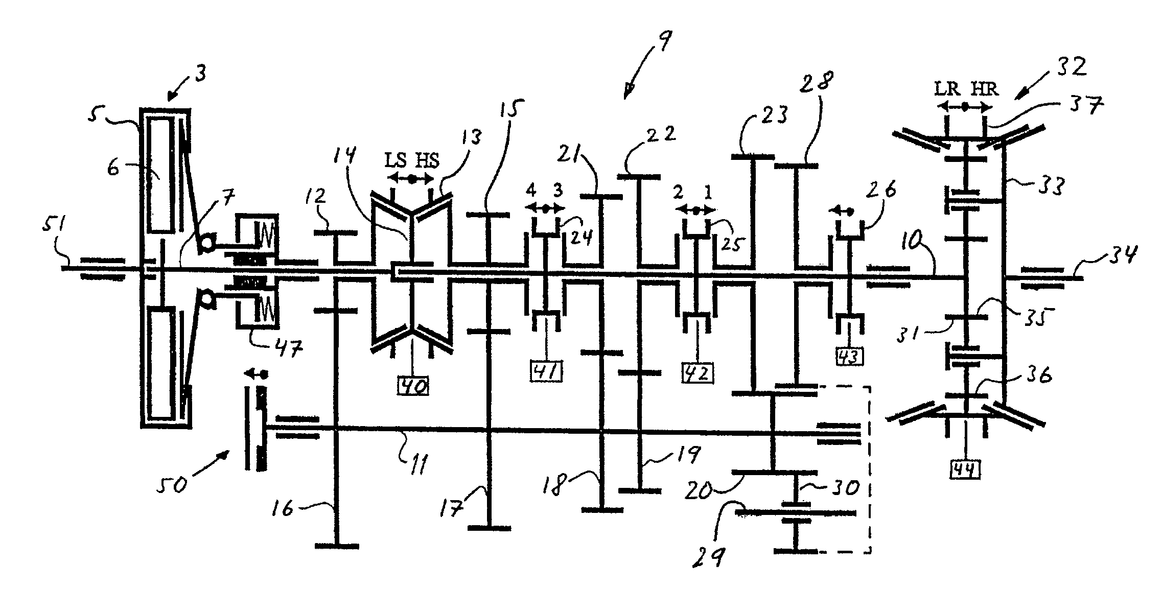
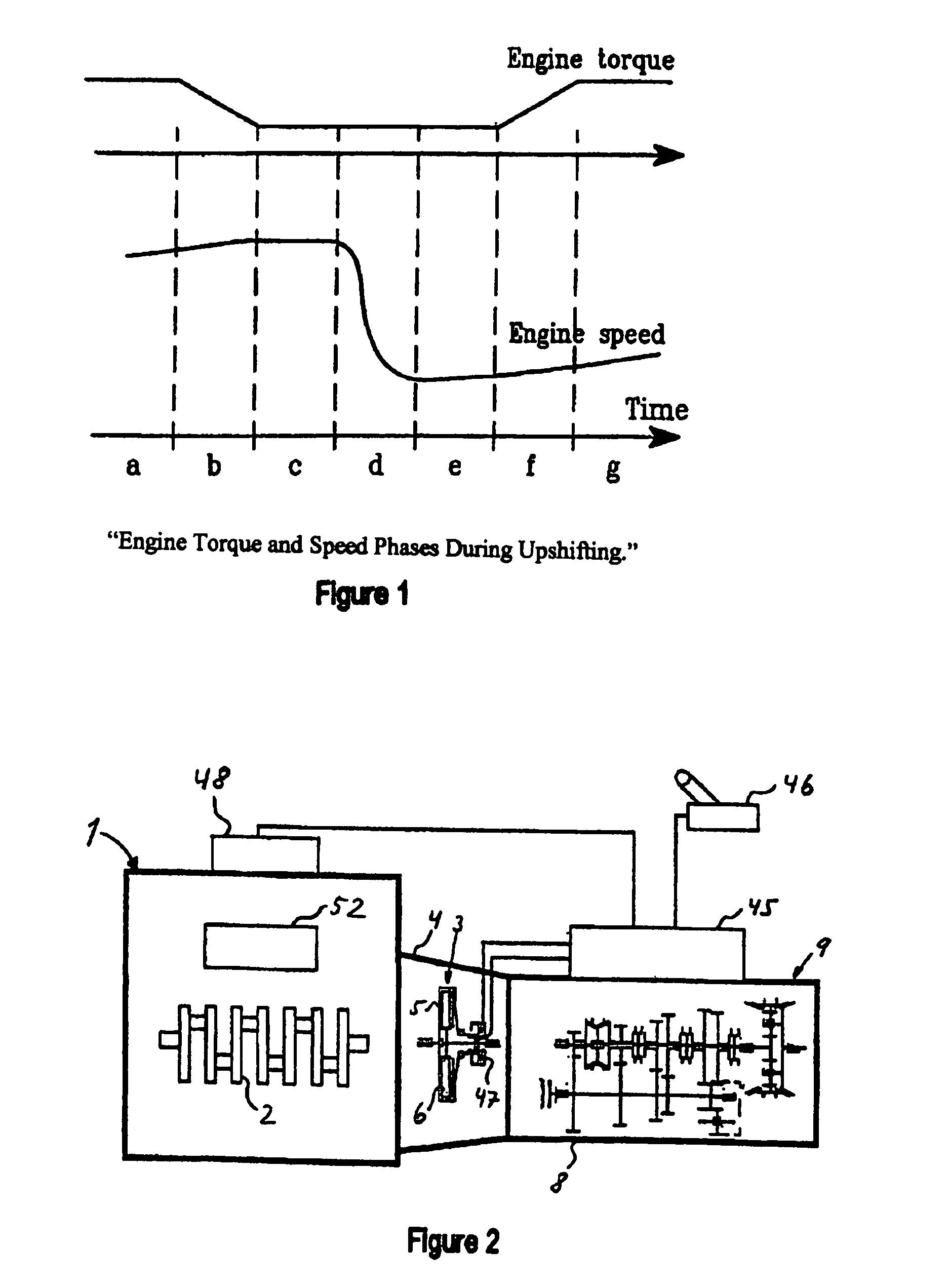
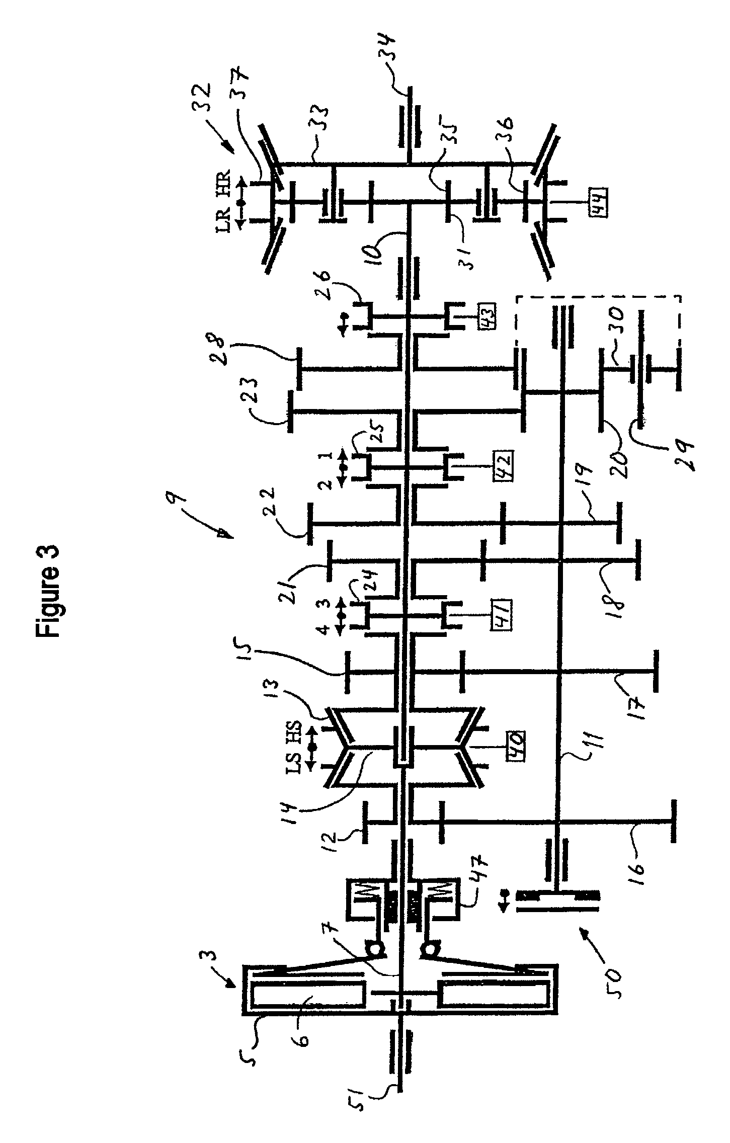
[0031]In FIG. 2, reference number 1 designates a six-cylinder internal combustion engine, for example a diesel engine, the crankshaft 2 of which is coupled to a single-plate dry disk clutch, designated generally by reference number 3, and which is enclosed in a clutch case 4. A two-plate version can be used instead of a single-plate disk clutch. The crankshaft 2 is, via the output shaft 51 of the engine (see FIG. 3), connected non-rotatably to the clutch housing 5 of the clutch 3, while a plate 6 thereof is non-rotatably connected to an input shaft 7 mounted rotatably in the casing 8 of a gearbox designated generally by reference number 9. A main shaft 10 and an intermediate shaft 11 are also rotatably mounted in the casing 8. Also illustrated are an engine control unit 48, a transmission control unit 45 and a manual gear selector 46 coupled to the transmission control unit 45. The transmission control unit 45 and the engine control unit 48 are adapted for communication with one ano...


PUM


Abstract

Method and arrangement for gear upshifting in a motor vehicle. The arrangement includes an internal combustion engine (1) with an engine-braking device (52), an automated disk-clutch (3), a multi-stage gearbox (9), in the casing (8) of which an input shaft (7), an intermediate shaft (11) and a main shaft (10) are mounted, and an intermediate shaft brake (50) for braking the intermediate shaft (11). When the upshifting takes place, the disk clutch (3) is disengaged and the intermediate shaft (11) is disengaged from the main shaft (10). The intermediate shaft brake (50) is activated so that the rotational speed of the intermediate shaft (11) is adapted to the next gear selected at the same time as the rotational speed of the engine (1) is adapted to the rotational speed of the input shaft (7) in the new gear by virtue of the engine-braking device (52) being activated.

Description

CROSS-REFERENCE TO RELATED APPLICATIONS[0001]The present application is a continuation patent application of International Application No. PCT / SE03 / 00734 filed 7 May 2003 now abandoned which was published in English pursuant to Article 21(2) of the Patent Cooperation Treaty, and which claims priority to Swedish Application No. 0201498-3 filed 17 May 2002. Said applications are expressly incorporated herein by reference in their entireties.FIELD OF THE INVENTION[0002]The present invention relates to a procedure for upshifting gear in a motor vehicle. The method and arrangement for implementing the invention includes an internal combustion engine with an engine-braking device, an automated disk-clutch and a multi-stage gearbox with braking means for braking an intermediate shaft arranged in the gearbox.BACKGROUND OF THE INVENTION[0003]In the instant application, the power plant comprises (includes, but is not necessarily limited to) an internal combustion engine, a disk clutch and gea...

Claims


Application Information

Patent Timeline
Patent Type & Authority Patents(United States)
IPC IPC(8): F16H3/08B60W10/10B60W10/18B60W30/18F16H37/02F16H61/02F16H61/04
CPCB60W10/111B60W10/196B60W30/19F16H61/0403B60K2741/286Y10T74/19223F16H2306/48F16H2306/54Y10T74/19233Y10T74/19219F16H2061/0411B60W10/02B60W10/06B60W10/10
Inventor LAURI, ERIKKARLSSON, SVANTESTEEN, MARCUS
Owner VOLVO LASTVAGNAR AB
Why Eureka
Try Eureka