Combined fuel injection valve-ignition plug

a fuel injector and valve ignition technology, which is applied in the direction of spark plugs, machines/engines, mechanical equipment, etc., can solve the problems of fuel injectors not allowing a sufficiently precise and reliable ignition, fuel injectors subject to constant worsening, and undefined spark arc-over position,

Inactive Publication Date: 2006-07-18
ROBERT BOSCH GMBH
View PDF21 Cites 83 Cited by
  • Summary
  • Abstract
  • Description
  • Claims
  • Application Information

AI Technical Summary

Benefits of technology

[0005]In contrast, the fuel injector-spark plug combination of the present invention has the advantage over the related art that the spark gap of the spark plug is sufficiently short that even low voltages are sufficient to generate an ignition spark. The spark gap has a width of between 50 and 300 μm, with an axial clearance of 3 to 15 mm in front of the spray-discharge orifice.

Problems solved by technology

A disadvantage of the conventional fuel injector with the integrated spark plug is that the position of the spark arc-over is undefined with respect to the fuel jet discharged from the spray-discharge orifice, since it is possible for the spark arc-over to occur at virtually any location in the lateral region of a valve-body projection.
Thus, the conventional fuel injector does not allow a sufficiently precise and reliable ignition of the so-called jet root of the fuel jet spray-discharged from the spray-discharge orifice.
Furthermore, the discharge orifice of the fuel jet may be subject to continually worsening carbon fouling or coking, which affects the form of the spray-discharged jet.
Another disadvantage is that the ceramic extrusion coat of the fuel injector is relatively cost-intensive.
It is also disadvantageous that the operating voltage required to generate an ignition spark normally amounts to up to 25 kV, so that, on the one hand, the components required for the voltage generation or voltage transformation are cost-intensive and require more space, and on the other hand, the components are subjected to heavy loads by the high voltages and therefore have a short service life.

Method used


Image

  • Combined fuel injection valve-ignition plug
  • Combined fuel injection valve-ignition plug
  • Combined fuel injection valve-ignition plug

Examples


Embodiment Construction

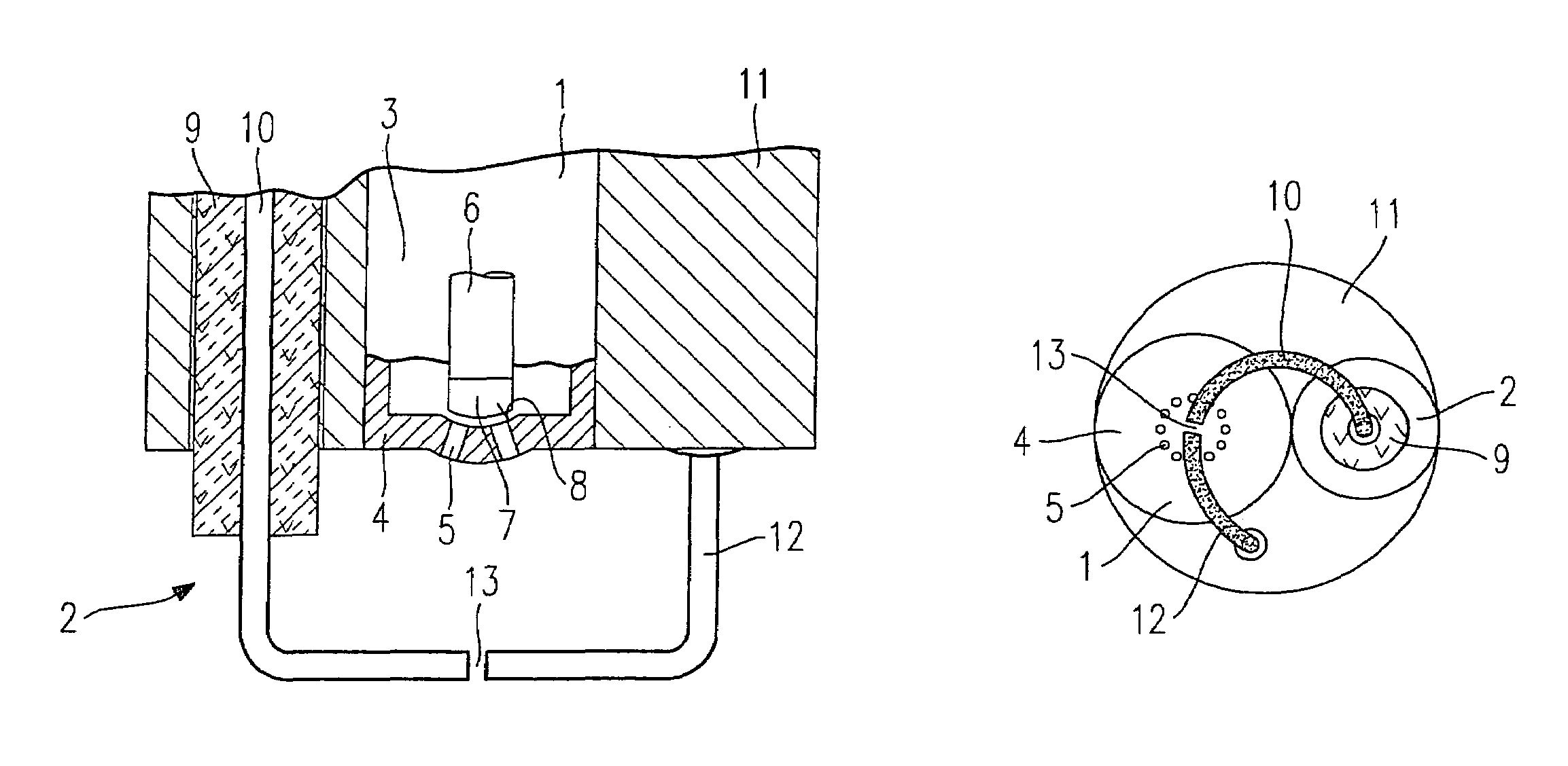
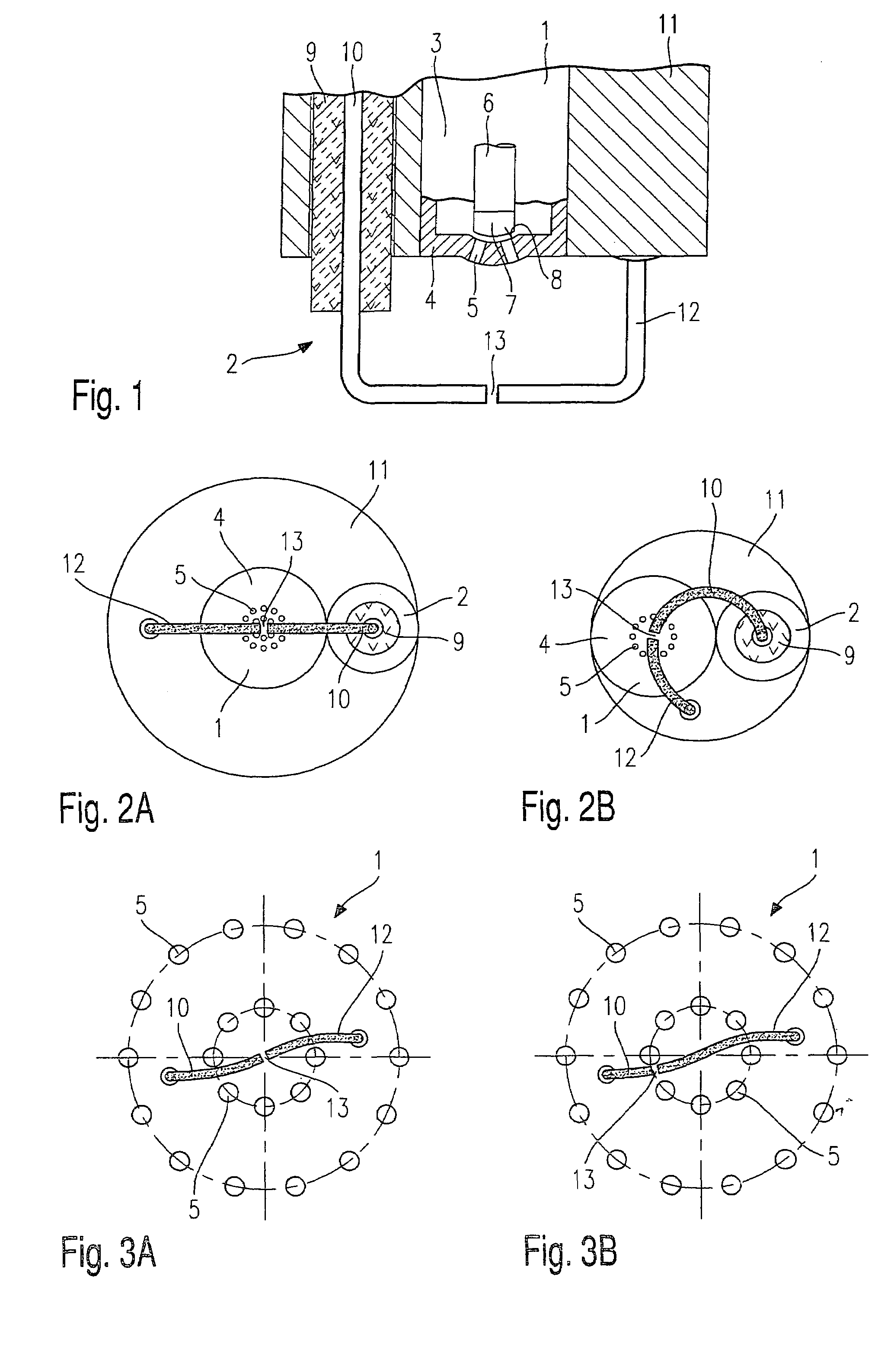
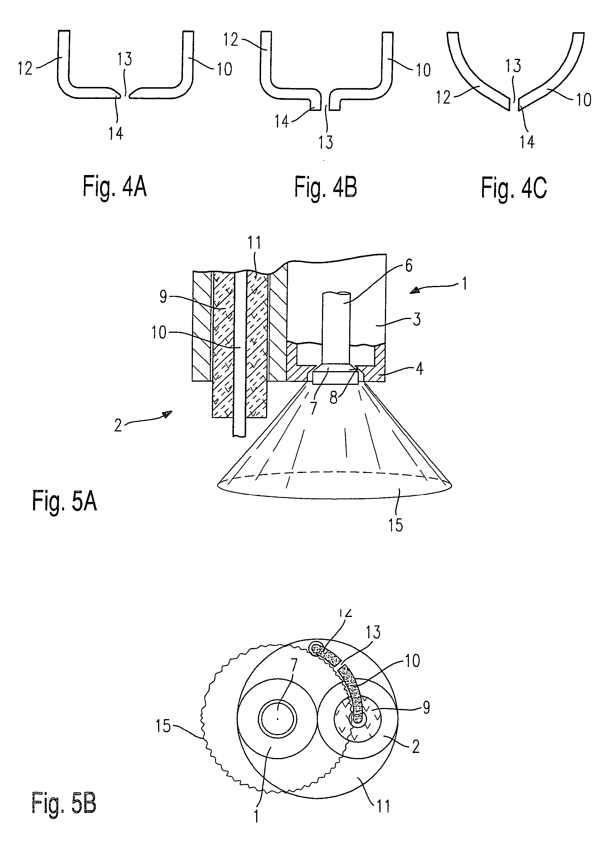
[0016]FIG. 1 shows a schematic partial longitudinal section of the end, on the spray-discharge side, of a fuel injector 1 having an integrated spark plug 2 (fuel injector-spark plug combination) for the direct injection of fuel into a combustion chamber of a mixture-compressing internal combustion engine having external ignition and for igniting the fuel injected into the combustion chamber.

[0017]Fuel injector 1 has a nozzle body 3 and a valve-seat member 4. A plurality of spray-discharge orifices 5 are arranged in valve-seat member 4; in the present exemplary embodiment, for example, there are five. Fuel injector 1 has a valve needle 6, which is disposed in nozzle body 3. At its spray-discharge side end, valve needle 6 has a valve-closure member 7, which forms a sealing seat together with a valve-seat surface 8 formed on valve-seat member 4. Shown in the present first exemplary embodiment of FIG. 1 is an inwardly opening fuel injector 1.

[0018]Fuel injector 1 may be configured as an...


PUM


Abstract

A fuel injector having an integrated spark plug is provided, the fuel injector providing direct injection of fuel into a combustion chamber of an internal combustion engine, and the spark plug for igniting the fuel injected into the combustion chamber. Also provided is a spark-plug insulator that insulates a first electrode and a second electrode which is set apart from the first electrode by a spark gap, the fuel injector and the spark-plug insulator of the spark plug being arranged in a shared housing. The spark gap has a width of 50 to 300 μm and is disposed in front of the fuel injector at a distance of 3 to 10 mm.

Description

FIELD OF THE INVENTION[0001]The present invention relates to a fuel injector having an integrated spark plug (fuel injector-spark plug combination).BACKGROUND INFORMATION[0002]A fuel injector having an integrated spark plug is described in European Patent 0 661 446. The fuel injector with integrated spark plug is used for the direct injection of fuel into the combustion chamber of an internal combustion engine and for igniting the fuel injected into the combustion chamber. Due to the compact integration of a fuel injector with a spark plug, it is possible to save installation space at the cylinder head of the internal combustion engine. The conventional fuel injector with integrated spark plug has a valve body, which forms a sealing seat together with a valve-closure member that is actuated by means of a valve needle. Adjacent to this sealing seat is a spray-discharge orifice, which discharges at an end face of the valve body facing the combustion chamber. A ceramic insulation eleme...

Claims


Application Information

Patent Timeline
Patent Type & Authority Patents(United States)
IPC IPC(8): F02M57/06H01T13/22F02P13/00
CPCH01T13/22F02M57/06
Inventor VOGEL, MANFREDHERDEN, WERNERECKER, RAINER
Owner ROBERT BOSCH GMBH
Why Eureka
Try Eureka