Exhaust gas heat exchanger

a heat exchanger and exhaust gas technology, applied in the direction of machines/engines, laminated elements, light and heating apparatus, etc., can solve the problems of degrading the durability of the tank, less efficiency in cooling the exhaust gas, etc., and achieve the effect of reducing the boiling of cooling water and low flow ra

Inactive Publication Date: 2006-07-18
DENSO CORP
View PDF12 Cites 54 Cited by
  • Summary
  • Abstract
  • Description
  • Claims
  • Application Information

AI Technical Summary

Benefits of technology

[0012]An object of the present invention is to provide an exhaust gas heat exchanger capable of eliminating the boiling of cooling water that may be caused by the sticking of the cooling water or caused by low flowing rate of the cooling water.

Problems solved by technology

The boiling of the cooling water may cause less efficiency about cooling of the exhaust gas flowing through the exhaust gas tubes 301, and / or rapid increase of inner pressure of the tank 302 that may degrade durability of the tank 302.

Method used


Image

  • Exhaust gas heat exchanger
  • Exhaust gas heat exchanger
  • Exhaust gas heat exchanger

Examples


first embodiment

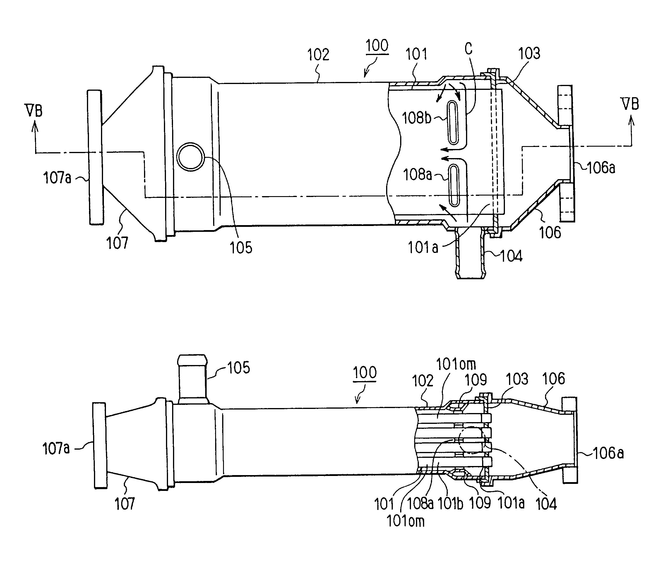
[0053]A first preferred embodiment of the present invention will be now described with reference to FIGS. 4, 5A and 5B. In the first embodiment, the present invention is typically applied to an EGR cooler of an exhaust gas recirculation system (EGR system) for a diesel engine 200 (internal combustion system). FIG. 1 shows an exhaust gas heat exchanger 100 (hereinafter, referred to as an EGR gas heat exchanger) that relates to the first embodiment and a second embodiment described later.

[0054]The EGR system includes an exhaust gas recirculation pipe 210 through which a part of the exhaust gas discharged from the engine 200 returns to an intake side of the engine 200. An EGR valve 220 for adjusting the amount of exhaust gas recirculation in accordance with an operational state of the engine 200 is disposed in the exhaust gas recirculation pipe 210. The EGR gas heat exchanger (EGR cooler) 100 is disposed between an exhaust gas side of the engine 200 and the EGR valve 220 so that heat e...

second embodiment

[0069]In the above embodiment, the ribs are used for leading the cooling water after colliding with the inner wall 102a of the tank 102 toward the upstream side of the exhaust gas tubes 101.

[0070]In this embodiment, instead of the ribs, partition walls (anti-reflection boards) are used to prevent the cooling water from flowing into the gaps formed between the inner wall of the tank 102 and the outermost exhaust gas tubes 101om.

[0071]As shown in FIGS. 6A, 6B, and 7, the exhaust gas tubes 101 are laminated in 4 layers as shown in the first embodiment. Moreover, they are divided into two parts in each layer thereof. Inner fins 101b and louvers 101c are formed in each exhaust gas tube 101. The louvers 101c fixed to the inner fines 101b are for causing vortex flow in the fine passages.

[0072]The partition walls 110(110a) are formed between the inner wall 102a of the tank 102 and the exhaust gas tubes 101. The partition walls 110a are formed by folding a plate to form the partition. That ...

third embodiment

[0076]In the above-described embodiments, the flow regulation of the cooling water has been discussed. In embodiments described later, the flow rate of fluid for cooling the exhaust gas flowing through the exhaust gas tubes, i.e., in this embodiment, the flow rate of cooling water will be discussed to prevent the cooling water from boiling locally.

[0077]An EGR cooler (i.e., an EGR gas heat exchanger) is perspectively shown in FIG. 8. EGR gas, i.e., exhaust gas from the engine 200 as shown in FIG. 4 flows into the EGR cooler at a right side in the figure, flows through the EGR cooler, and then, flows out from the EGR cooler at a left side in the figure. Cooling water flows into the EGR cooler through a cooling water inlet pipe (a fluid inlet) 204 to exchange heat with the exhaust gas flowing through the EGR cooler. The cooling water flows out from the EGR cooler through a cooling water outlet pipe 205 (a fluid outlet).

[0078]In FIG. 8, XI—XI and XII—XII mean cross sectional view point...


PUM


Abstract

An exhaust gas heat exchanger has a tank, laminated exhaust gas tubes where the exhaust gas flows, a cooling water inlet pipe and a cooling water outlet pipe. The cooling water flows into the tank and flows through water passages between adjacent exhaust gas tubes and between an inner wall of the tank and an outermost exhaust gas tube. Ribs are formed on the exhaust gas tubes so as to lead the cooling water after colliding with an inner wall toward an upstream side of the exhaust gas tubes to prevent the cooling water from being stuck. Otherwise, spaces between an inner wall of a casing and the exhaust gas tubes are regulated to keep the flow rate of the cooling water in the casing so that the cooling water is prevented from being boiled locally by slow flow rate of the cooling water.

Description

CROSS REFERENCE TO RELATED APPLICATION[0001]This application is based upon Japanese Patent Applications No. 2001-209335, filed on Jul. 10, 2001, No. 2002-7333, filed on Jan. 16, 2002, and No. 2002-494, filed on Jan. 7, 2002.BACKGROUND OF THE INVENTION[0002]1. Field of the Invention[0003]The present invention relates to an exhaust gas heat exchanger for performing heat exchange between exhaust gas generated by combustion and cooling water. Specifically, the present invention relates to an exhaust gas heat exchanger for cooling the exhaust gas in an exhaust gas recirculation system (i.e., EGR system).[0004]2. Related Art[0005]As shown in FIGS. 1A and 1B, as a prototype made by the inventors, an exhaust gas heat exchanger for cooling the exhaust gas in an EGR system (hereinafter, referred to as an EGR gas heat exchanger 300) can be equipped with plural laminated exhaust gas tubes 301 disposed in a tank 302 having a rectangular sectional pipe shape. The exhaust gas tubes 301 have a flat...

Claims


Application Information

Patent Timeline
Patent Type & Authority Patents(United States)
IPC IPC(8): F28D7/16F28F9/013F01N5/02F02M25/07F28F3/02F28F3/04F28F9/02F28F13/06
CPCF01N5/02F02M25/0737F28D7/1684F28F3/025F28F3/044F28F13/06F28D21/0003F28F2009/029Y02T10/121Y02T10/16F28F2275/04F28F2240/00F28F9/0219F02M26/32Y02T10/12
Inventor HAYASHI, TAKAYUKIMAEDA, AKIHIRO
Owner DENSO CORP
Why Eureka
Try Eureka