
Viscous damper for machinery mounting

a damper and machinery technology, applied in the field of vibration dampers, can solve the problems of affecting the stability of the mounting system, affecting the stability of the machine, and being subject to shock and vibration, and achieving the effects of reducing or eliminating shock and vibration, and improving the vibration isolation mounting system

Inactive Publication Date: 2006-07-18
VIBRODYNAMICS
View PDF14 Cites 10 Cited by
  • Summary
  • Abstract
  • Description
  • Claims
  • Application Information

AI Technical Summary

Benefits of technology

[0006]In accordance with the present invention, there is provided an improved vibration isolating mounting system for machinery, or the like, for at least a portion of a load positioned or arranged on a substructure, such as a building floor. The vibration isolating mount includes a horizontally disposed top member or platform engageable with at least a portion of the load (e.g., the foot of a machine), and a bottom member disposed beneath the top member and spaced therefrom. The vibration isolating mounting system includes a damping member disposed between the top member or platform and the bottom member to decrease or deaden vibrations caused by external and internal forces. The damping member comprises a viscous vibration damper to minimize or substantially eliminate shock and vibrations, and is incorporated in and useful of a machinery mount for supporting at least a portion of a load to be positioned on a substructure such as the floor of a building.
[0008]It will be observed that the receptacle or vessel is affixed to the bottom member so as to enclose the bottom of this vessel, and the plunger is affixed to the top member or platform to enclosed the top of the plunger. Where desired, the receptacle or vessel and the plunger may be provided with an enclosed end, which is then affixed to the bottom member and top member, respectively, but is preferably affixed, each at its marginal edge or perimeter to the bottom member and to the top member. In order to provide sufficient strength to the unit, there is provided at least one strengthening member of still smaller dimensions than the plunger so as to be disposed interiorily of the plunger. The strengthening member extends downwardly from the top platform and terminates at the perforated plate, so as to enhance the strength of the damping unit.
[0009]It should be understood that the receptacle and plunger may have any desired cross-section, as viewed in plan, including circular, rectangular, and elliptical, and that the configuration of each such member is the same, as viewed in horizontal cross-section. It will be observed that the side walls of each such member are therefore parallel, as viewed in vertical cross-section. Further, the walls of each such member are spaced equally from an adjacent member to provide a fluid movement in that region that achieves maximum damping.

Problems solved by technology

Extremely heavy loads such as machinery, equipment, presses, and the like, are subjected to shock and vibration and are susceptible to misalignment due to these forces and / or due to settling including settling of the building floor or building foundation.
Heavy machinery, for example punch presses standing twenty feet or higher and weighing as much as a million pounds or more, can be damaged or become misaligned.

Method used


Image

  • Viscous damper for machinery mounting
  • Viscous damper for machinery mounting
  • Viscous damper for machinery mounting

Examples


Embodiment Construction

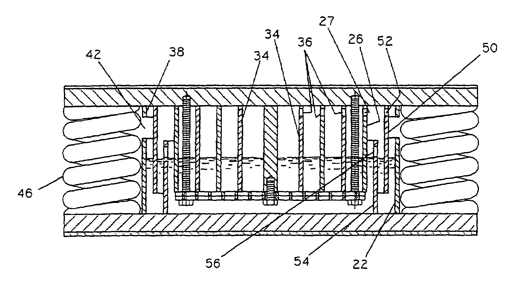
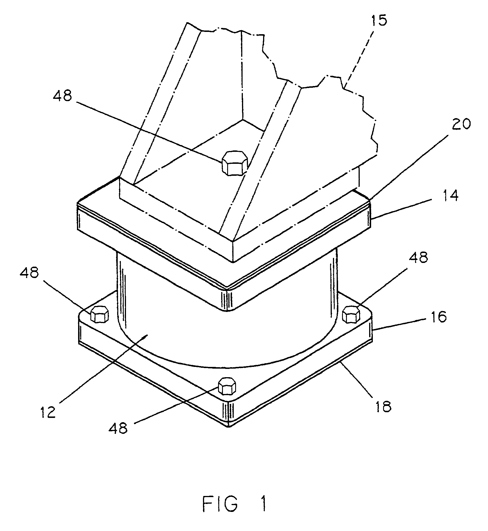
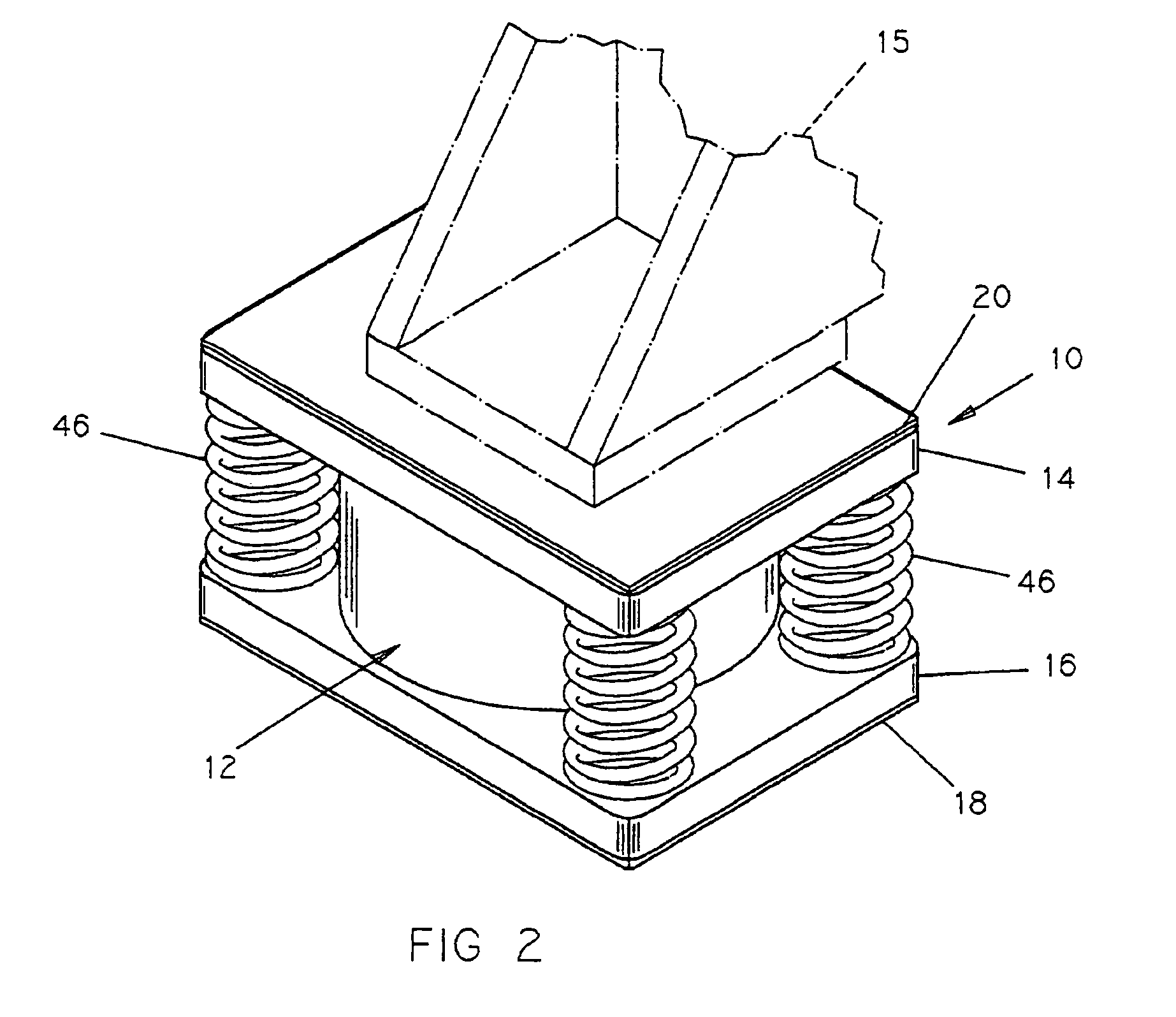
[0025]In referring to the drawings, wherein like reference numerals designate similar parts throughout the several views, there is illustrated in FIG. 1 a machine mounting system or isolator, generally indicated by the numeral 10, to absorb vibrations and shock. The machinery mount 10 is illustrated more specifically in FIGS. 2 and 3, and is a vibration isolation mounting system incorporating the features of a viscous damper. The machine mounting system 10 includes a damper, indicated generally by the numeral 12 and described below in detail, a horizontally disposed top member or platform 14 for supporting a load 15, and a bottom or bearing member 16 seated on a substructure (not shown) spaced below the top member. The load member 15, shown in phantom, may be a foot of a heavy machine seated on the top member or platform 14, which typically has a substantially planar top surface. The bottom or bearing member 16 is positioned on a substructure such as the floor of a building (not sho...


PUM


Abstract

A viscous damper for a machinery mount having a damping member disposed intermediate a top support engageable with at least a portion of a load and a bottom plate disposed beneath the support and spaced therefrom to thereby decrease or deaden vibrations. The damper includes a receptacle for vertical disposition, which is closed at the bottom and opened at the top, and is adaptable for containing a viscous fluid. A plunger of smaller lateral dimensions is arranged concentrically and co-axially within the receptacle, and depends downwardly from the horizontally disposed support, and is of such a longitudinal dimension as to be spaced from the closed bottom of the receptacle so as to be submerged partially in the viscous fluid and is therefore free to move vertically. A perforated plate is affixed at the bottom of the plunger, and provides fluid communication between the receptacle and the plunger. The damping effected by the vibrations will force the viscous medium through the apertures in the bottom plate in one direction or the other.

Description

CROSS REFERENCE TO RELATED APPLICATION[0001]This application is a continuation-in-part of U.S. Ser. No. 09 / 935,262, filed Aug. 22, 2001 now abandoned.FIELD OF THE INVENTION[0002]This invention relates to a vibration damper. More specifically, this invention relates to a viscous damper, incorporated in a machinery mounting or isolator system, to substantially decrease or deaden vibrations caused by forces external or internal to the machine.BACKGROUND AND PRIOR ART[0003]Extremely heavy loads such as machinery, equipment, presses, and the like, are subjected to shock and vibration and are susceptible to misalignment due to these forces and / or due to settling including settling of the building floor or building foundation. (As used herein and in the appended claims, the term “machinery” is used generically, and is intended to include all such machinery, equipment, apparatus, etc.) Proper alignment, including leveling, flatness, and the like, is essential in order to operate efficiently...

Claims


Application Information

Patent Timeline
IPC IPC(8): F16F7/10F16M13/00F16F9/16F16F13/00F16F15/02F16F15/023
CPCF16F9/16F16F15/023F16F15/022F16F13/00
Inventor FOLKENS, JERRY D.REINKE, HAROLD E.VEROEVEN, STEVEN M.BASTL, JOSEPH L.
Owner VIBRODYNAMICS
Learn More