Rear shelf for motor vehicle equipped with a folding roof

Inactive Publication Date: 2006-07-18
SOC EUROENNE DE BREVETAB AUTOMOBILES
View PDF19 Cites 11 Cited by
  • Summary
  • Abstract
  • Description
  • Claims
  • Application Information

AI Technical Summary

Benefits of technology

[0019]Thus, when the central element of the panel passes into the retracted position, its lateral elements pivot in a simple fashion with respect to

Problems solved by technology

One problem is however posed because, when the panel passes from one position to the other, its lateral edges may be interfered with by the

Method used


Image

  • Rear shelf for motor vehicle equipped with a folding roof
  • Rear shelf for motor vehicle equipped with a folding roof
  • Rear shelf for motor vehicle equipped with a folding roof

Examples


first embodiment

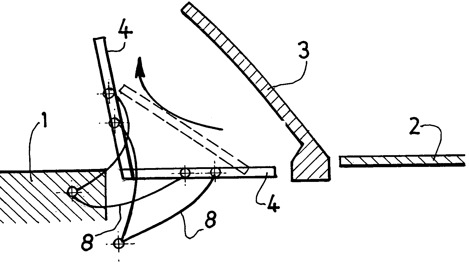
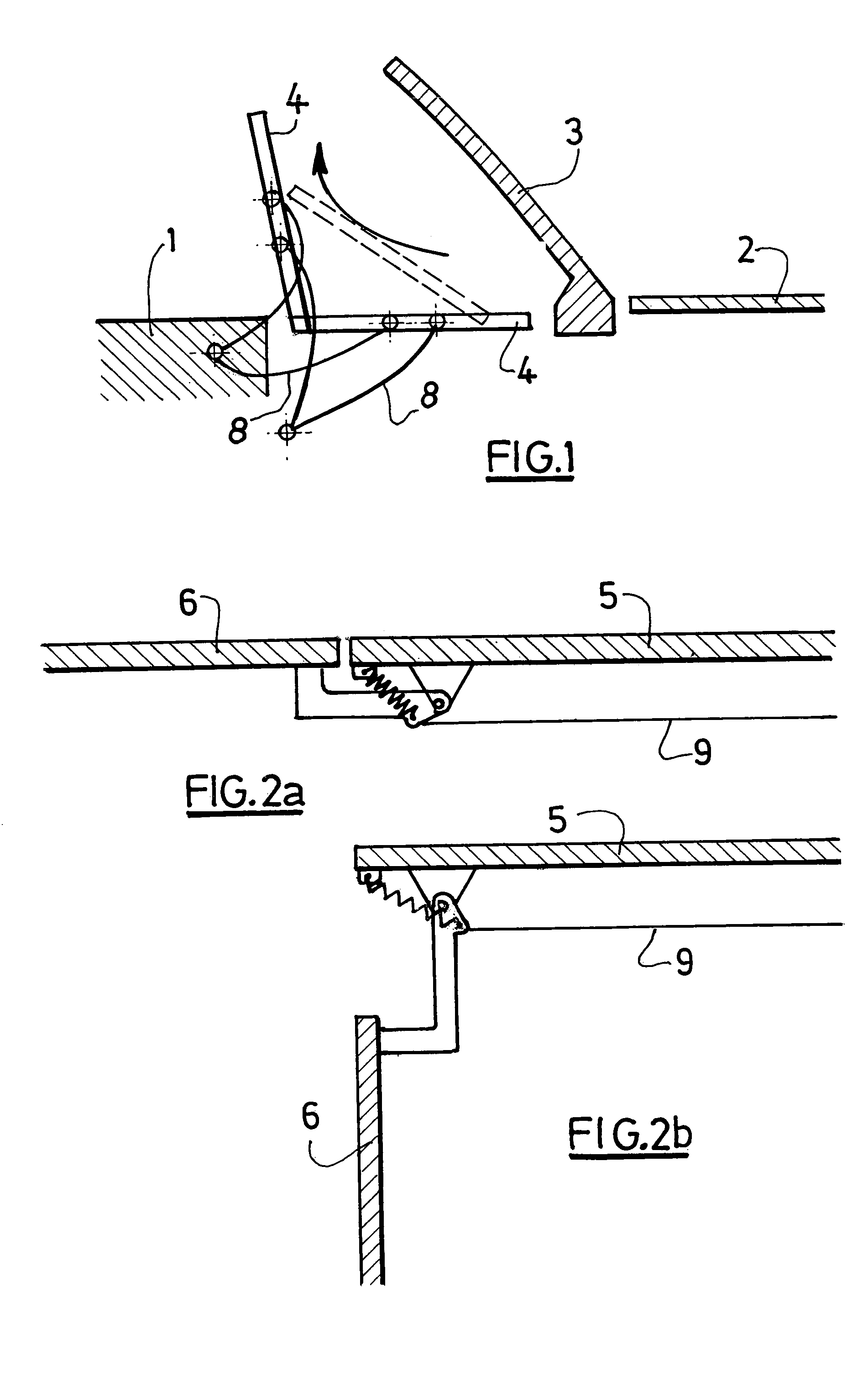
[0033] illustrated by FIGS. 1 to 3, the lateral elements 6 are retracted towards the bottom of the vehicle, so that it is not necessary to withdraw the roof before the panel 4 is moved.

[0034]To this end, according to a first variant, illustrated by FIGS. 1 and 2, articulated arms 8 are provided, fixed by one end to the panel 4 and by the other end to the chassis 1. A linkage 9 directly mounted on these arms 8 (FIG. 2) makes it possible, by means of a system of connecting rods (not shown), to make the lateral elements 6 pivot downwards.

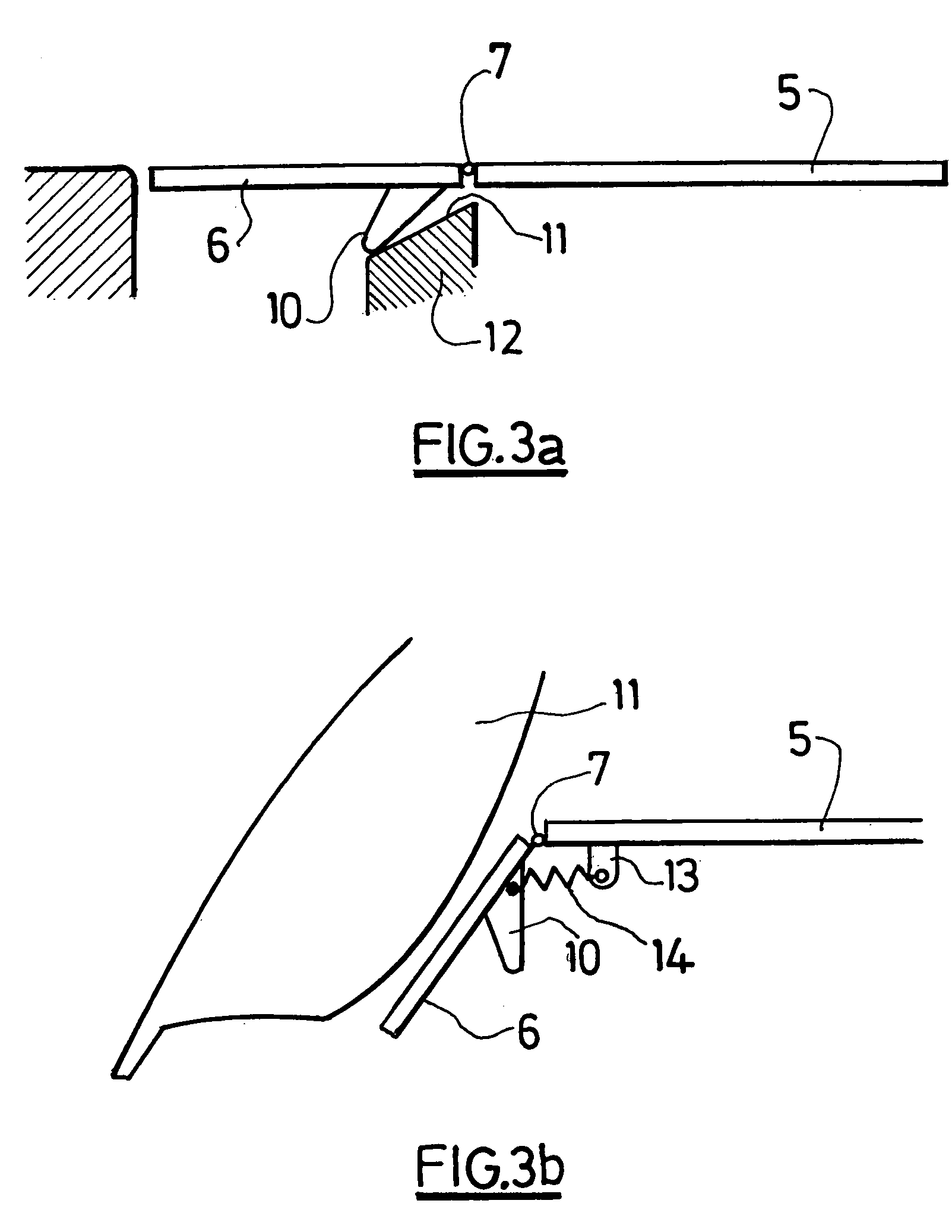
[0035]According to a second variant of the first embodiment (FIG. 3), the downward pivoting of the lateral elements 6 is achieved by means of a lug 10 fixed to the lateral elements 6. This lug 10 constitutes a cam follower able to cooperate with a cam track 11 situated on a support 12 fixed to the chassis 1.

[0036]A spring 14 disposed between the lug 10 and a lug 13 situated on the central element 5 of the panel is arranged so as to cause such a pivotin...

second embodiment

[0037] illustrated by FIGS. 4a and 4b, the lateral elements 6 are retracted towards the top of the vehicle, so that it is necessary to withdraw the roof by any suitable means prior to the movement of the panel 4.

[0038]To this end, the lateral elements 6 are provided with a cam follower 15 in the form of a swan neck, the end of which is mounted so as to pivot rotationally on the central element 5 of the panel 4. This cam follower 15 is arranged so as to cooperate with a cam track 17 situated on the support 12 fixed to the chassis 1.

[0039]A return spring 18 is fixed on the one hand to the nose 19 of the cam follower 15 and on the other hand to a lug 20 situated on the panel. This spring 18 makes it possible to apply the nose 19 of the cam follower 15 to the cam track 17, when the panel 4 is in a position of use (FIG. 4a). Then, when the panel 4 is raised, the spring 18 drives the nose 19 of the cam follower 15 upwards, this movement causing the lifting of the lateral element 6 and its...


PUM


Abstract

A motor vehicle roof can fold from a position of use to a retracted position in a rear boot of the motor vehicle. The roof has a central element and a pair of lateral elements, each rotatably attached at one of two transverse edges of the central element. A mechanism connected between each lateral element and the central element cooperates with features carried on a chassis of the vehicle to cause the lateral elements to rotate into an inclined position respective the central element as the roof folds into the retracted position. The mechanism also causes the lateral elements to rotate as the roof moves into the position of use.

Description

BACKGROUND OF THE INVENTION[0001]1. Field of the Invention[0002]The present invention concerns a rear panel for a motor vehicle provided with a roof which can be folded in its rear boot, more particularly for such a vehicle comprising means able to make the said panel pass from a position of use in which it is disposed generally substantially horizontally between a chassis element of the vehicle and the front edge of a lid of the said boot, and a retracted position in which it is disposed generally substantially vertical so as to leave clear a passage space for the said roof between the said chassis element and the said edge.[0003]2. Description of the Prior Art[0004]Such rear panels are already known which pivot from the position of use to the retracted position for the entry or exit of the roof in the rear boot.[0005]One problem is however posed because, when the panel passes from one position to the other, its lateral edges may be interfered with by the internal trim of the rear ...

Claims


Application Information

Patent Timeline
IPC IPC(8): B60J7/00B60J7/12B60J7/20
CPCB60J7/203B60J7/202B60J7/12
Inventor GUILLEZ, JEAN-MARCQUEVEAU, PAULQUEVEAU, GERARD
Owner SOC EUROENNE DE BREVETAB AUTOMOBILES
Why Eureka
Try Eureka