Solar reflection panels

a solar reflection and solar panel technology, applied in the field of solar collector panels, can solve the problems of silver corrosion of the mirror and consequent loss of solar reflectivity, and achieve the effect of low cost and low cos

Inactive Publication Date: 2006-07-18
SANDIA NAT LAB
View PDF5 Cites 64 Cited by
  • Summary
  • Abstract
  • Description
  • Claims
  • Application Information

AI Technical Summary

Benefits of technology

[0015]A primary advantage of the present invention is the relative low cost materials used to construct the solar collector.
[0016]Another advantage of the present invention is the relative low cost manufacturing process used to construct the solar collector.
[0017]Other objects, advantages and novel features, and further scope of applicability of the present invention will be set forth in part in ...

Problems solved by technology

However, many problems surfaced with a majority of the solar collectors, such as the formation of dimples due to adhesion forces exerted on the gla...

Method used


Image

  • Solar reflection panels
  • Solar reflection panels

Examples


example 1

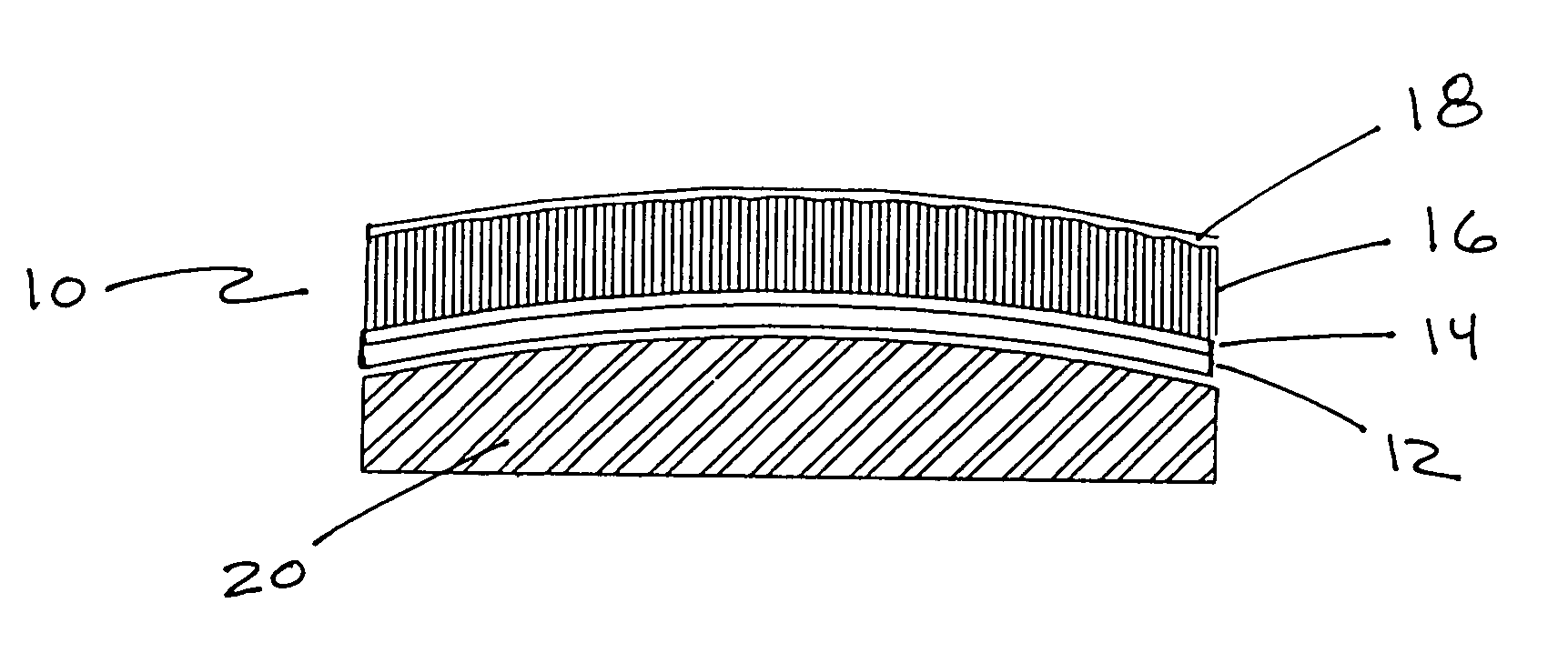
[0030]Two techniques have been employed to produce sandwich-type construction panels—vacuum bagging and foam-in-place. In vacuum bagging, the glass / steel laminate was laid mirror surface down onto a mandrel (as shown in FIG. 1). Adhesive was applied to the back of the glass / steel laminate and to one side of the back steel skin. A core material was placed between the steel skins in contact with the adhesive. The sandwich was then covered with and sealed inside a plastic sheet and a partial vacuum was applied. The partial vacuum results in a high and uniform clamping force that facilitates the curing process, and forces the steel and glass sheets to conform to the pre-determined shape of the mandrel. Vacuums ranging from 381 to 584 mm of mercury (15 to 23 inches of mercury) were used. The inverse curvature of the mandrel is translated or locked into the composite panel.

[0031]A mirror segment was laid face down on the table, adhesive was pulled from the roll and stuck down at the far e...

example 2

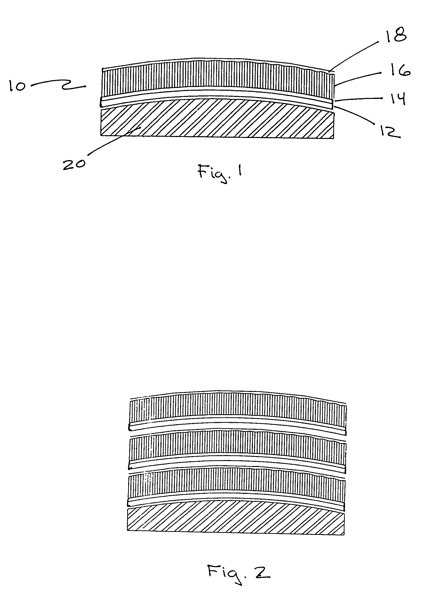
[0038]The foam in place technique was performed exclusively with two-part urethane foams. Typically, a North Carolina Foam Industries, Inc. pour-in-place system (#811-91) was used. Typical foam density ranged from about 70.4 kg / m3 to 83.3 kg / m3 (4.4 to 5.2 lb / ft3) and was inversely proportional to cure temperature. With this technique, the glass / steel laminate was laid mirror surface down on the mandrel, as in the vacuum bag technique. The two-part urethane foam was then mixed, poured, and spread onto the back of the glass / steel laminate. The back steel sheet was then placed directly onto the foam. A frame spaced at a set distance from the mandrel secured the back steel sheet in place as the foam expanded and forced the foam to ooze from the sides of the sandwich. The force of the expanding foam forced the glass / steel laminate to conform to the mandrel. After the foam cured, the curvature of the mandrel was locked into the composite panel. The frame was then removed and the excess f...


PUM


Abstract

A solar collector comprising a glass mirror, and a composite panel, wherein the back of the mirror is affixed to a front surface of the composite panel. The composite panel comprises a front sheet affixed to a surface of a core material, preferably a core material comprising a honeycomb structure, and a back sheet affixed to an opposite surface of the core material. The invention may further comprise a sealing strip, preferably comprising EPDM, positioned between the glass mirror and the front surface of the composite panel. The invention also is of methods of making such solar collectors.

Description

GOVERNMENT RIGHTS[0001]The Government has rights to this invention pursuant to Contract No. DE-AC04-94AL85000 awarded by the U.S. Department of Energy.BACKGROUND OF THE INVENTION[0002]1. Field of the Invention (Technical Field)[0003]The present invention relates to solar collector panels and the methods of making the same.[0004]2. Background Art[0005]Low-cost / high-performance solar collectors are needed to make solar thermal power competitive with other power sources. Incorporation of mirrors into commercially viable panels is the key to low-cost, high-performance solar collectors. In the 1970's and 1980's and with the financial support of the U.S. government, substantial development and test activities were directed toward the development of glass reflector designs for central receiver heliostats, parabolic trough collectors, and point focus concentrators (“solar collectors”). However, many problems surfaced with a majority of the solar collectors, such as the formation of dimples ...

Claims


Application Information

Patent Timeline
IPC IPC(8): G02B7/182
CPCF24J2/1057G02B5/10G02B7/183G02B7/181Y02E10/40F24S23/82
Inventor DIVER, JR., RICHARD B.GROSSMAN, JAMES W.RESHETNIK, MICHAEL
Owner SANDIA NAT LAB
Why Eureka
Try Eureka