
Electronic component storing case and electronic device

a technology of electronic components and storage cases, applied in the direction of coupling device connections, electrical apparatus casings/cabinets/drawers, instruments, etc., can solve the problems of short recording medium capacity, inability to add new data, and inability to record new data

Inactive Publication Date: 2006-07-18
CANON KK +1
View PDF11 Cites 27 Cited by
  • Summary
  • Abstract
  • Description
  • Claims
  • Application Information

AI Technical Summary

Benefits of technology

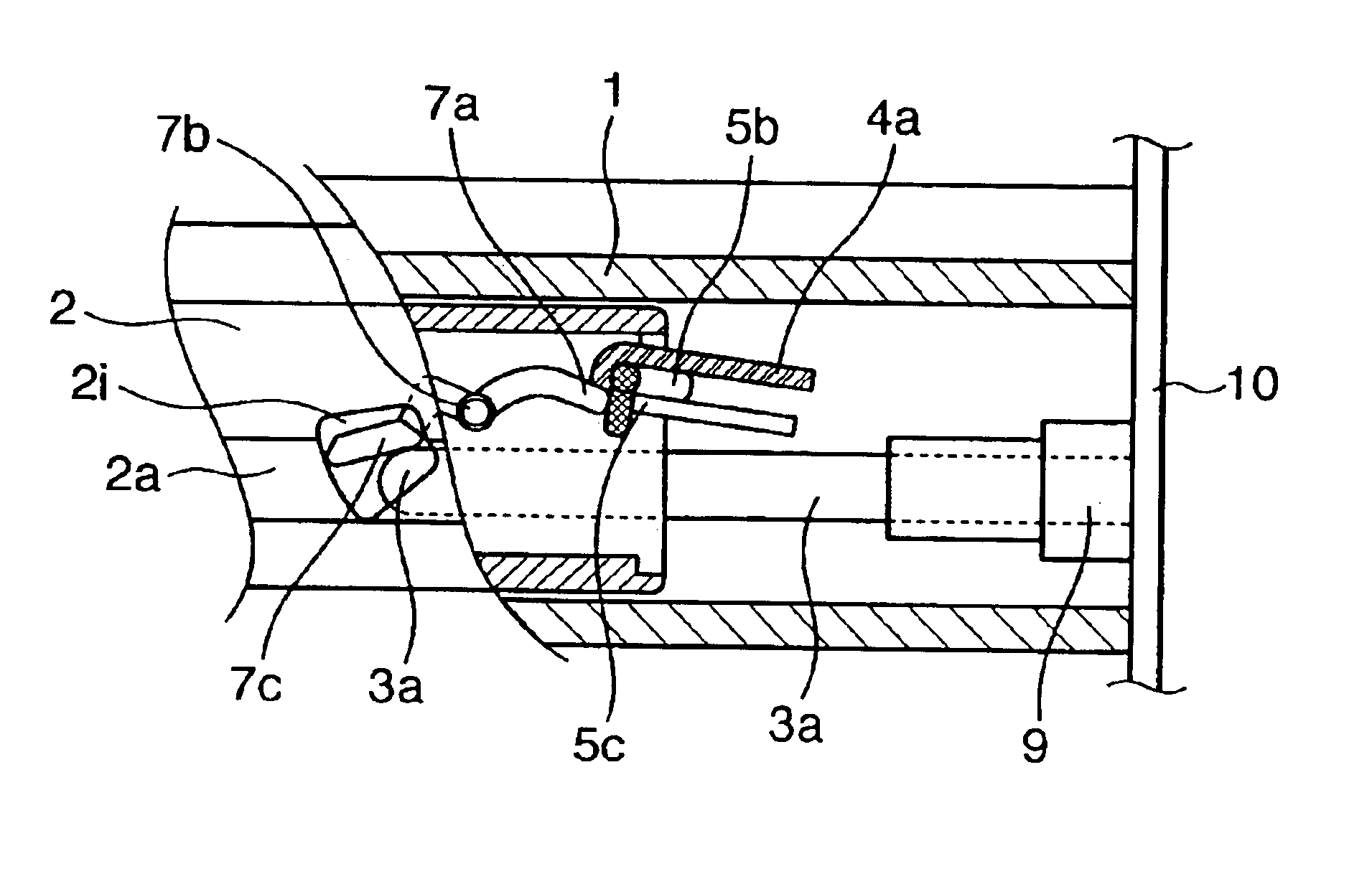
[0011]The present invention has been made in view of the problems described above, and has as its object to make it possible to arrange an electronic device at a position close to the casing of the housing while providing a shutter that protects the connector from the outside when the electronic device is removed from the main body equipment.

Problems solved by technology

When the volume of data to be recorded increases, if the recording medium is stationarily incorporated in the equipment and cannot be replaced easily, the capacity becomes short, and new data cannot be additionally recorded unless overwriting it on the recorded data.
Particularly, with a recording method in which a process such as MPEG (Moving Picture Experts Group) compression is not performed, the problem of the short capacity of the recording medium is obvious.
Then, the HDD becomes unguarded against dust or static electricity accumulated in the human body, or a metal piece or the like may accidentally come into contact with the connector to damage the electronic circuit in the HDD.
In particular, with a removable HDD incorporating a small HDD, since it is often removed and carried around because of its excellent portability, the problem described above is more obvious.
This is disadvantageous in equipment whose portability is the primary concern.
Also, the fitting length of the connection-side connector 13 inevitably becomes large.
In connection of equipments that perform high-speed serial transmission with a transmission frequency of several gigabits / sec to several ten gigabits / sec, not only the signal transmission energy loss increases, but also the impedance mismatch tends to easily occur, and ambient noise tends to be picked up easily to increase the jitter.
As a result, high-speed signal transmission suffers.
If the structure as shown in FIG. 14 is employed in portable equipment or the like, the portable equipment becomes very thick in a direction perpendicular to the inserting / mounting direction, and the portability suffers.
When identical shutter structures must be arranged vertically adjacent to each other in a multiple of levels, an unwanted space further increases, and the whole equipment cannot but become large.
The resultant structure becomes very difficult to open and close, which is not practical.

Method used


Image

  • Electronic component storing case and electronic device
  • Electronic component storing case and electronic device
  • Electronic component storing case and electronic device

Examples


Embodiment Construction

[0032]Preferred embodiments of the present invention will now be described in detail in accordance with the accompanying drawings.

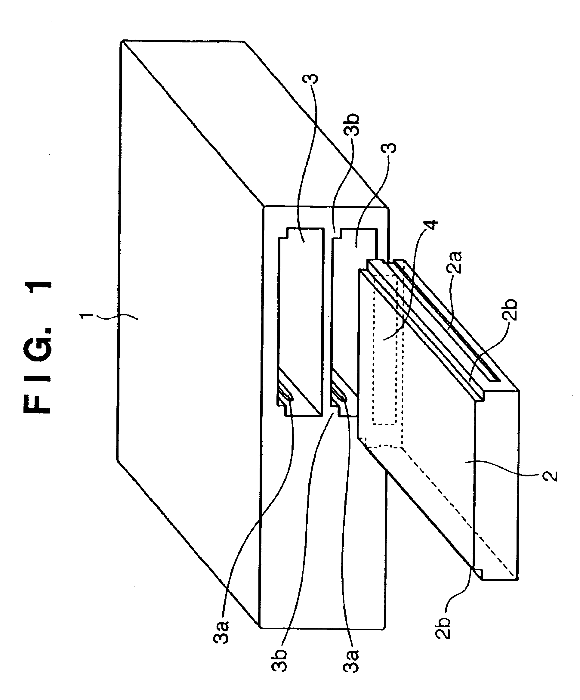
[0033]FIG. 1 is a view showing the entire arrangement of an electronic equipment system in which an electronic device 2 incorporating a hard disk therein is to be detachably mounted in an electronic equipment main body 1. Referring to FIG. 1, two slots 3, in each of which the electronic device 2 is to be inserted and mounted, are formed in the front surface of the electronic equipment main body 1. The electronic device 2 is inserted in the electronic equipment main body 1 through the opening of the slot 3, so that a connecting connector provided in the electronic equipment main body 1 and a connector provided to the electronic device 2 are electrically connected to each other.

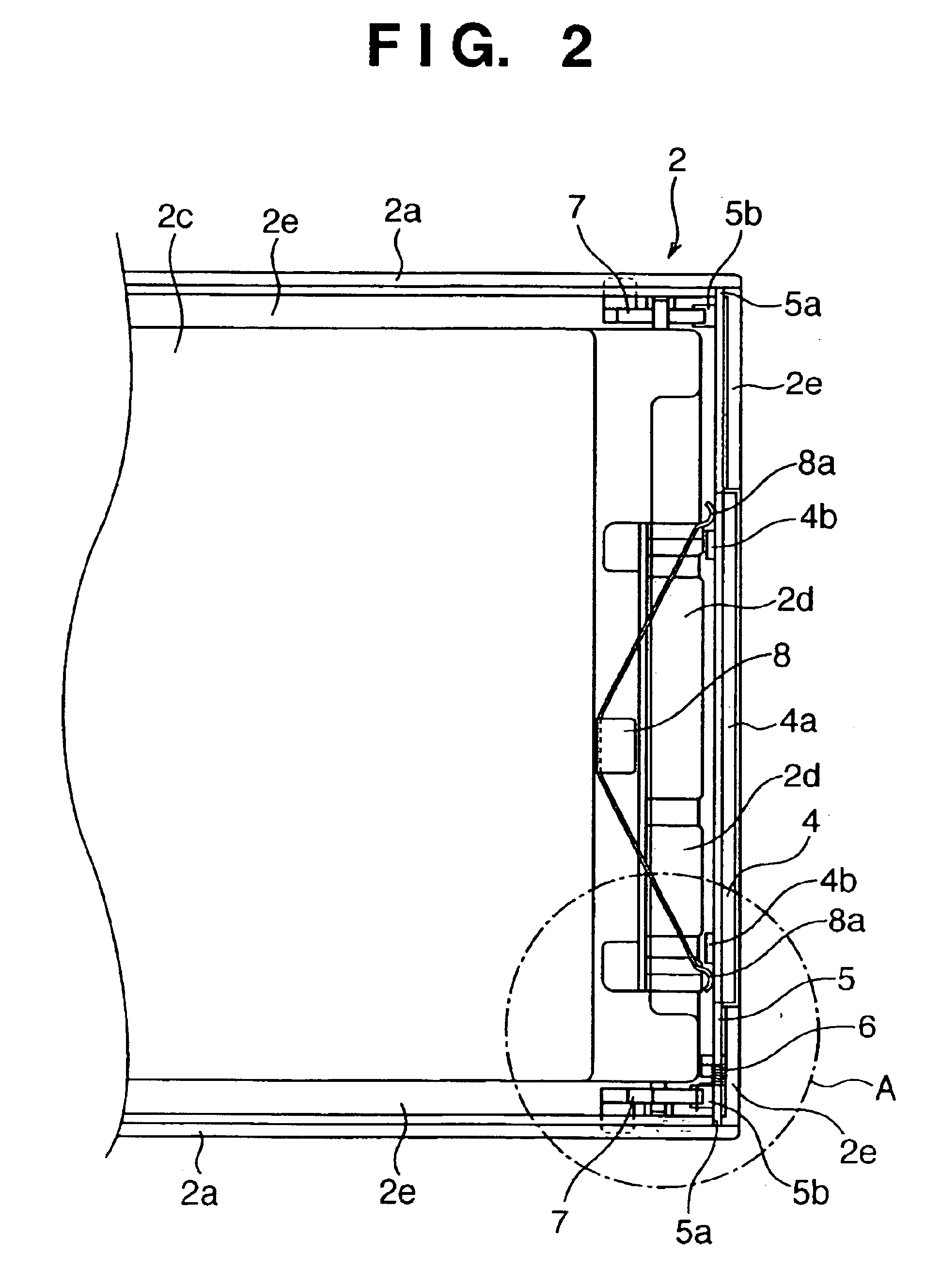
[0034]A shutter 4 is arranged at the distal end in the inserting direction of the electronic device 2. When the electronic device 2 is removed from the electronic equipment main body...


PUM


Abstract

An electronic component storing case capable of accommodating an electronic component includes a case member having an opening in its first end face, a shutter member which is arranged in the opening of the case member, pivotal outwardly to open / close the opening, and biased in a closing direction by a first resilient member, and a lever member which has a first end extending to an outside of the case member from at least its one side surface perpendicular to the first end face of the case member, and a second end which acts on the shutter member. The lever member converts an operating force to be applied to the first end into a biasing force for biasing the shutter member in an opening direction.

Description

FIELD OF THE INVENTION[0001]The present invention relates to a connection structure for electrically connecting an electronic equipment main body having an information processing function and an electronic device incorporating a storage medium or electronic component therein to each other and, more particularly, to a shutter opening / closing structure for a connection interface connector in a portable electronic device which is detachably connected to an electronic equipment main body.BACKGROUND OF THE INVENTION[0002]In general, as a recording medium often used by electronic equipment such as a personal computer (PC) having an information processing function, a semiconductor recording medium, magnetic recording medium, a magneto-optical storage medium or the like which holds information therein is used. Digital data to be recorded and accumulated in such a recording medium is not limited to text data consisting of characters, but also includes still images of a digital still camera a...

Claims


Application Information

Patent Timeline
IPC IPC(8): H01R13/44H05K5/02G11B33/02G11B33/12H01R13/453H01R13/52H05K5/03H05K7/14
CPCG06K13/0875G11B33/027H01R13/4536G11B33/123H01R2201/06H01R13/4534
Inventor SUWA, KANAMEANDO, MASAHIROTOMIKAWA, TADAAKI
Owner CANON KK
Learn More