

Leadframe-to-plastic lock for IC package
- Summary
- Abstract
- Description
- Claims
- Application Information
AI Technical Summary
Benefits of technology
Problems solved by technology
Method used
Image

Examples
Embodiment Construction
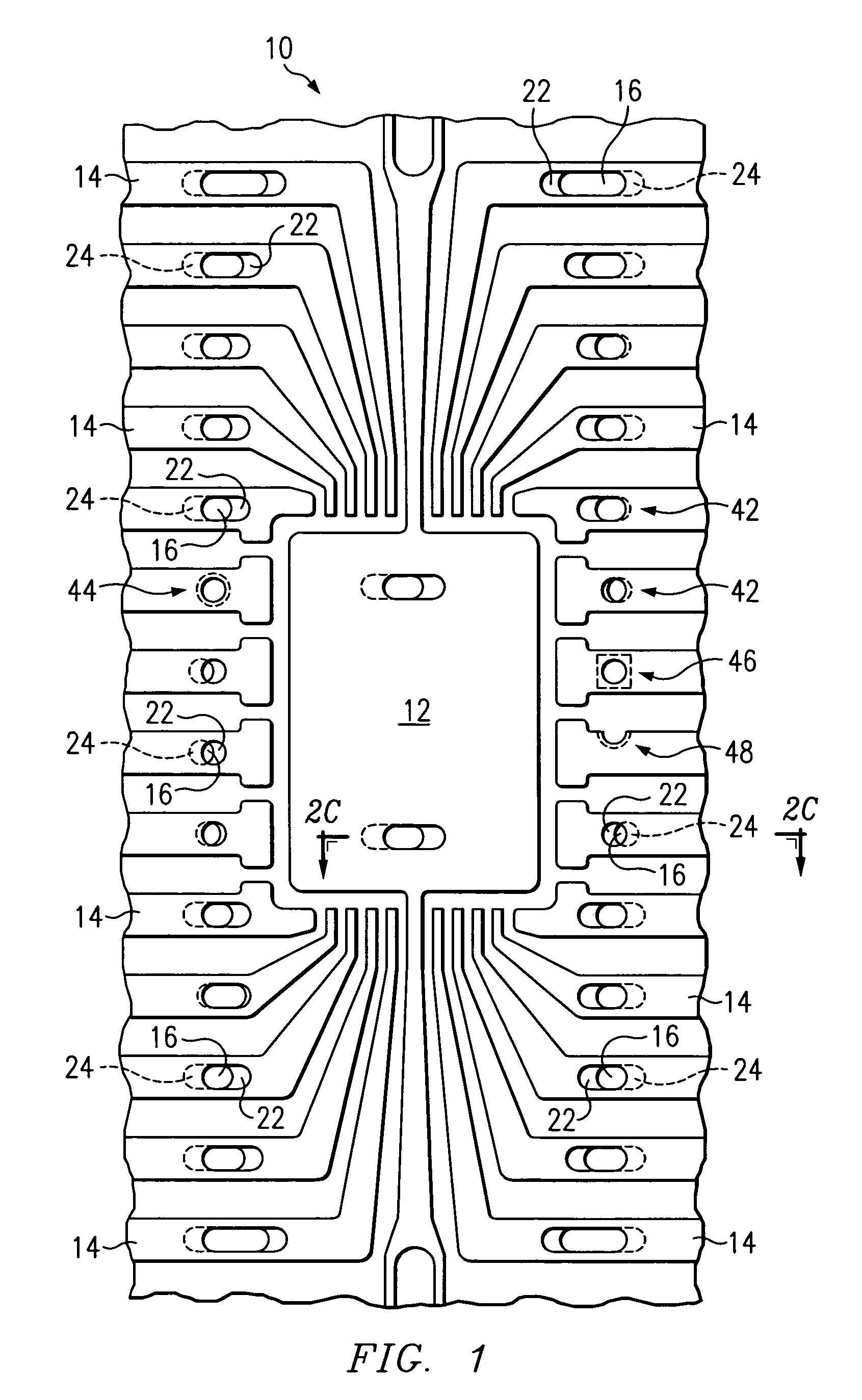
[0021]In general, the invention provides an IC package leadframe mold lock and methods for making the same. Representatively illustrated in FIG. 1 is a top view of an example of a leadframe 10 according to a preferred embodiment of the invention. The leadframe 10 has a die pad 12 and numerous lead fingers 14. According to this exemplary embodiment both the die pad 12 and each of the lead fingers 14 have perforating apertures 16. It should be understood that the invention may alternatively be implemented with various combinations of apertures 16 in either the die pad 12, some or all of the lead fingers 14, or both, as further described.
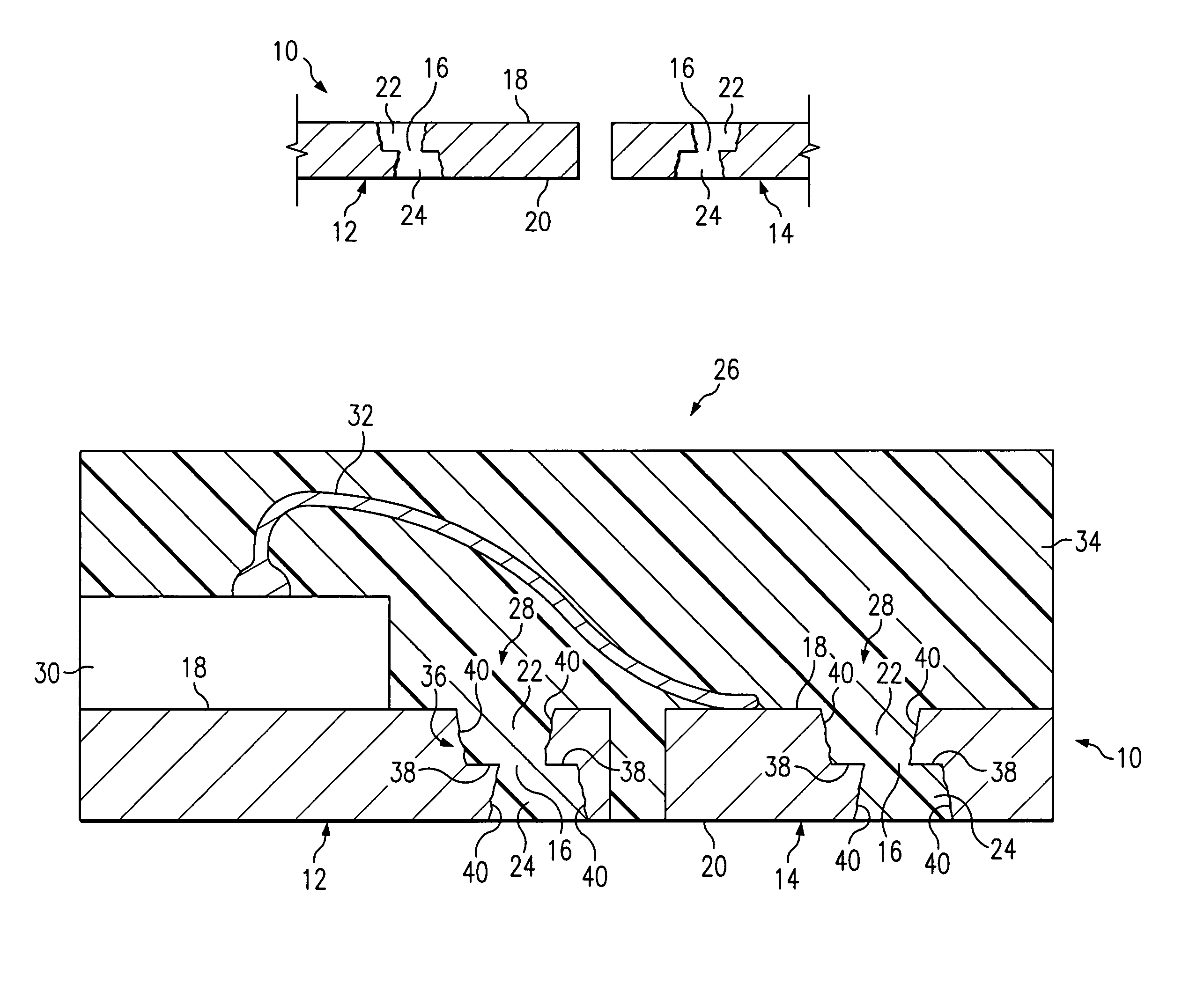
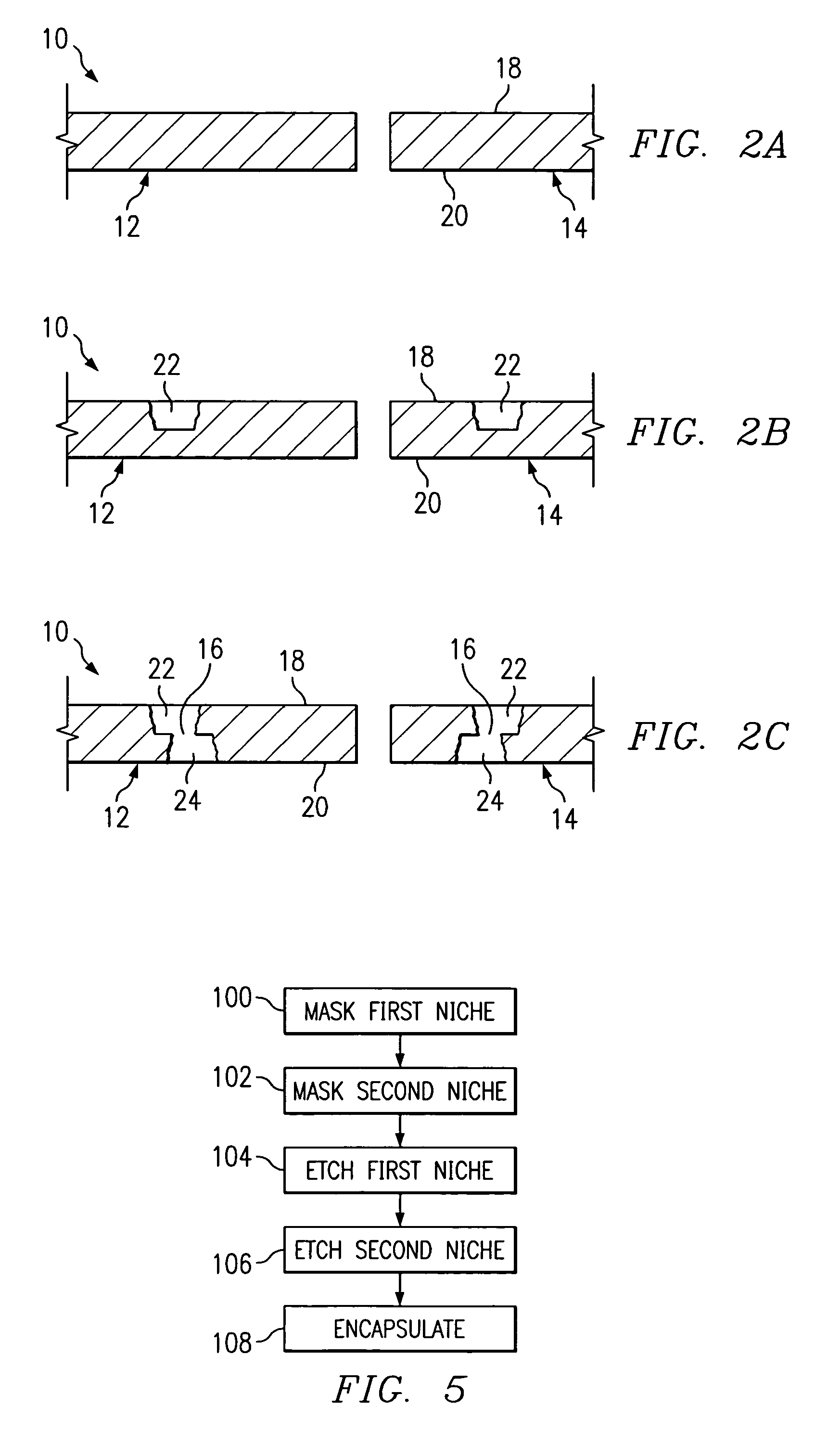
[0022]As may be seen in FIG. 2C, which is a sectional view of the portion of the lead frame 10 of FIG. 1 taken along line C—C, the apertures 16 are located within the leadframe material and neither at the top 18 nor at the bottom20 surfaces of the leadframe 10. Preferably the apertures are formed by partially etching opposed niches 22, 24 in the leadfr...
PUM
 Abstract
Description
Claims
Application Information