Capacitive-load driving circuit capable of properly handling temperature rise and plasma display apparatus using the same
a technology of driving circuit and temperature rise, which is applied in the direction of instruments, television systems, and electrodes, etc., can solve the problems of increasing component cost, reducing power consumption reduction design effectiveness, and reducing the effect of power consumption reduction design
- Summary
- Abstract
- Description
- Claims
- Application Information
AI Technical Summary
Problems solved by technology
Method used
Image
Examples
first embodiment
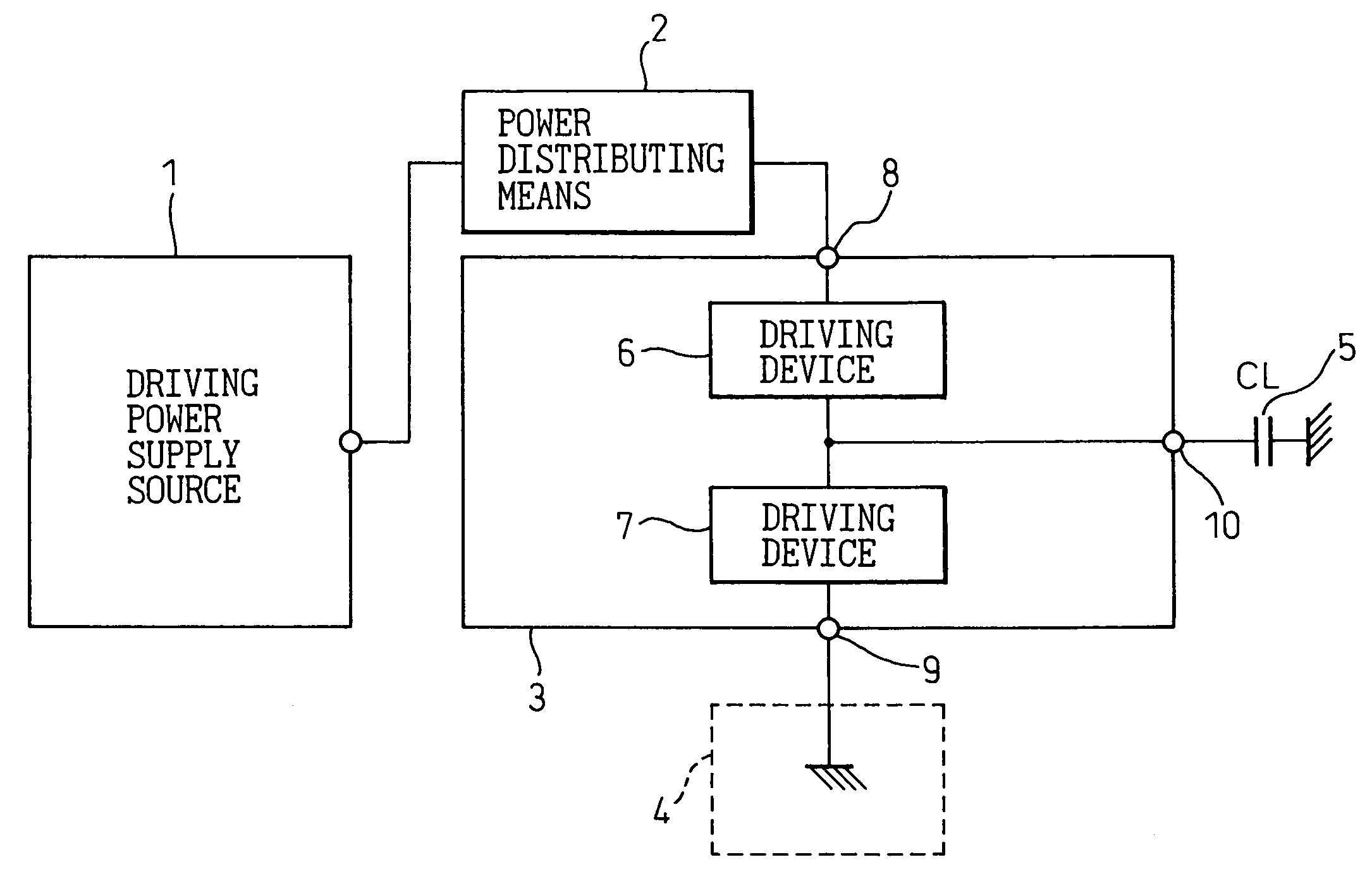
[0079]FIG. 4 is a block diagram showing the capacitive-load driving circuit according to the present invention. In FIG. 4, reference numeral 1 is a driving power supply source, 21 is a power distributing means, or circuit, 3 is an address drive IC, 4 is a reference potential point (ground point), 5 is a load capacitor, 6 and 7 are driving devices, 8 and 9 are a power supply terminal and a reference potential terminal (ground terminal), respectively, of the address drive IC, and 10 is an output terminal of the address drive IC.
[0080]As shown in FIG. 4, in the first embodiment, the power distributing means, or circuit, 21 is inserted between the driving power supply source 1 and the high-level voltage supply terminal 8 of the address drive IC 3; this power distributing means is constructed as a resistive impedance (resistive element) 21 whose value is higher than about one-tenth of the resistive impedance that the driving device 6 provides at the time of conduction (the resistive comp...
second embodiment
[0082]FIG. 5 is a block diagram showing the capacitive-load driving circuit according to the present invention.
[0083]As shown in FIG. 5, in the second embodiment, the power distributing means in the foregoing first embodiment is constructed as a constant-current source 22. With the driving circuit of the second embodiment, the effective value of the current flowing in the driving device 6 can be made the smallest under the same driving conditions; as a result, theoretically, the power consumption of the driving circuit 3 can be reduced to the lowest value.
[0084]FIG. 6 is a circuit diagram showing one example of the constant-current source in the capacitive-load driving circuit shown in FIG. 5.
[0085]As shown in FIG. 6, the constant-current source 22 comprises an n-channel MOS transistor (nMOS transistor) 221 whose gate-to-source voltage is biased, for example, to a constant voltage by a zener diode 222. As shown, a resistor 225 may be connected in series to the source of the transist...
fourth embodiment
[0090]FIG. 9 is a block diagram showing the capacitive-load driving circuit according to the present invention.
[0091]In the fourth embodiment, the switches 12, 13, and 14 in the driving power supply source 1 of FIG. 7 described above are replaced by nMOS transistors 121, 131 / 132, and 141, respectively, whose gate voltages are controlled by a driving power control circuit 15, thus making the driving power supply source 1 also perform the function of the power distributing means using the constant-current sources as in the second embodiment shown in FIG. 5. In the fourth embodiment, diodes 130 and 1301 are connected in series to the drains of the transistors 131 and 132 but, instead, these diodes may be inserted in series to the sources of the transistors 131 and 132. Further, in FIG. 9, the switches in the driving power supply source 1 are constructed from nMOS transistors, but it will be appreciated that use can also be made of other active devices such as pMOS transistors or bipola...
PUM
 Abstract
Description
Claims
Application Information
 - R&D
- Intellectual Property
- Life Sciences
- Materials
- Tech Scout
- Unparalleled Data Quality
- Higher Quality Content
- 60% Fewer Hallucinations
Browse by: Latest US Patents, China's latest patents, Technical Efficacy Thesaurus, Application Domain, Technology Topic, Popular Technical Reports.
© 2025 PatSnap. All rights reserved.Legal|Privacy policy|Modern Slavery Act Transparency Statement|Sitemap|About US| Contact US: help@patsnap.com


