Rotation angle detecting device

a detection device and rotation angle technology, applied in the direction of measurement devices, instruments, magnetic measurements, etc., can solve the problems of increased cost, lowered detection accuracy of the rotation angle of the magnet 107 with the rotation of the object to be measured, and increased components and assembly steps. the effect of increasing the linearity of the output signal

Inactive Publication Date: 2006-07-18
DENSO CORP
View PDF8 Cites 14 Cited by
  • Summary
  • Abstract
  • Description
  • Claims
  • Application Information

AI Technical Summary

Benefits of technology

[0009]An object of the present invention is to provide a rotation angle detecting device capable of improving detection accuracy of a rotation angle of an object to be measured by improving linearity of an output signal from a magnetic detection element with respect to rotation angles of the object to be measured and a magnet over a full range of a detected angle of the object to be measured. Moreover, an object of the present invention is to provide a rotation angle detecting device capable of preventing the detection accuracy of the rotation angle of the magnet rotating with the rotation of the object to be measured from being lowered by constituting a housing for rotatably holding the magnet therein and a housing for retaining magnetic members and the magnetic detection element therein by a single component.
[0011]As a result, since an output signal from the magnetic detection element is also suddenly lowered, the output signal approaches an ideal output signal as compared with that in the conventional techniques. Therefore, linearity of the output signal from the magnetic detection element (linearity of an output variation characteristic of the magnetic detection element) with respect to rotation angles of the object to be measured and the magnet over a full range of the detected angle of the object to be measured can be improved. In particular, since the linearity of the output signal from the magnetic detection element (the linearity of the output variation characteristic of the magnetic detection element) with respect to the rotation angle of the magnet in an area where the air gap is relatively small can be improved, the detection accuracy of the rotation angle of the object to be measured can be improved.
[0013]According to still another aspect of the present invention, by providing a sensor retaining section for retaining a rotation angle sensor including magnetic members and a magnetic detection element, and a magnet holding hole for rotatably holding a magnet therein for a housing integrally formed of a non-magnetic material, a housing for rotatably holding the magnet therein and a housing for retaining the magnetic members and the magnet detection element therein can be constituted by a single component. As a result, the positional accuracy (combination accuracy) of the magnetic members and the magnetic detection element with respect to the magnetization direction of the magnet can be easily obtained, thereby reducing a variation in assembly of the magnet and the magnetic members and the magnetic detection element. Moreover, since a variation is hardly generated in output from the magnetic detection element, the detection accuracy of the rotation angle of the magnet rotating with the rotation of the object to be measured can be prevented from being lowered. Moreover, since a single magnet is provided as a magnetic field source, the number of components and the number of assembly steps can be reduced as compared with those in the conventional techniques requiring two magnets. As a result, the overall cost of the rotation angle detecting device can be reduced.
[0014]According to still another aspect of the present invention, the magnetic detection gap between the magnetic members is provided in the middle of the magnetic circuit including the magnet and the magnetic members so that a positional relation is such that a density of magnetic flux crossing both magnetically sensitive faces of the magnetic detection element in the plate-thickness direction becomes relatively small with respect to a magnetization direction of the magnet when the rotation angle of the object to be measured is positioned in the vicinity of the middle angle within the range of use. As a result, if the object to be measured is positioned in the vicinity of the middle angle within the range of use, the density of the magnetic flux passing through the magnetic detection gap between the magnetic members, that is, the density of the magnetic flux crossing both magnetically sensitive faces of the magnetic detection element in the plate-thickness direction becomes relatively small. Therefore, an output signal from the magnetic detection element has a relatively small value, thereby detecting the rotation angle of the object to be measured in the vicinity of the middle angle. Then, if the magnet rotates in both directions from the vicinity of the middle angle, the output from the magnetic detection element elevates or drops so as to accurately detect the rotation angle of the object to be measured over a wide range.
[0015]According to yet another aspect of the present invention, magnetic detection element retaining pieces, each having a smaller width than that of the reverse warp parts for concentrating the magnetic flux of the magnet thereon, are provided for the magnetic members, respectively. Then, if the respective magnetic detection element retaining pieces of the magnetic members are provided so as to be opposed to each other through the magnetic detection gap while being in contact with both magnetically sensitive faces of the magnetic detection element in the plate-thickness direction, the magnetic flux can be concentrated on both magnetically sensitive faces of the magnetic detection element in the plate-thickness direction. As a result, the magnetic flux can be concentrated on both magnetically sensitive faces of the magnetic detection element in the plate-thickness direction efficiently over the range of the rotation angle in which the magnet rotates from the minimum angle to the maximum angle with the rotation of the object to be measured, that is, over a full range of the detected angle of the object to be measured. Therefore, a stable output signal can be obtained from the magnetic detection element.
[0016]According to yet another aspect of the present invention, shoulder parts extended in an approximately straight manner in a direction approximately perpendicularly crossing a center axis direction so as to be separated away from each other are provided for the magnetic members, respectively. Then, through bent parts bent at an approximately acute angle at ends of the shoulder parts, the ends of the shoulder parts and the ends of the reverse warp parts are connected to each other. The respective magnetic detection element retaining pieces of the magnetic members are provided so as to be bent at an approximately right angle at the ends of the shoulder parts on the magnetic detection gap side so as to be separated away from the magnet. As a result, the magnetic flux can be concentrated on both magnetically sensitive faces of the magnetic detection element in the plate-thickness direction efficiently over the range of a rotation angle in which the magnet rotates from the minimum angle to the maximum angle with the rotation of the object to be measured, that is, a full range of the detected angle of the object to be measured. Therefore, a stable output signal can be obtained from the magnetic detection element.

Problems solved by technology

As a result, there arises a problem that detection accuracy of the rotation angle of the magnets 107 rotating with the rotation of the object to be measured is lowered.
Moreover, since two magnets 107 are provided as magnetic field sources, the number of components and the number of assembly steps are increased, resulting in a problem of increased cost.
As a result, there arises a problem that linearity of the output value of the Hall IC 110 with respect to the rotation angle of the magnet 130, which rotates with the rotation of the object to be measured, is degraded within the range of the detected angle of the object to be measured.

Method used


Image

  • Rotation angle detecting device
  • Rotation angle detecting device
  • Rotation angle detecting device

Examples


first embodiment

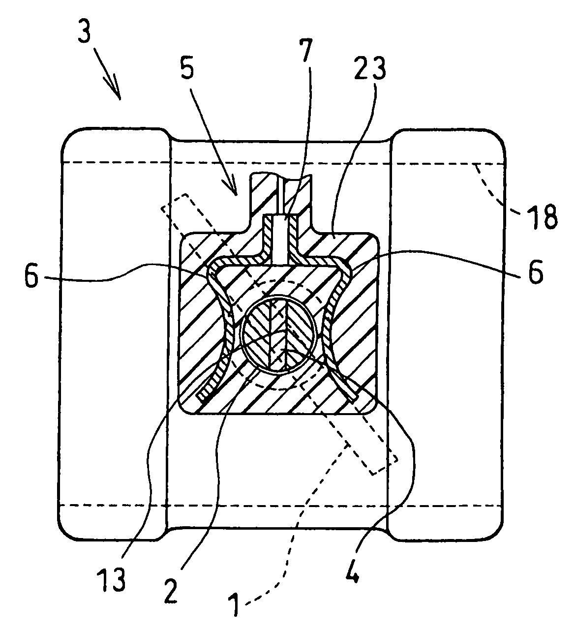
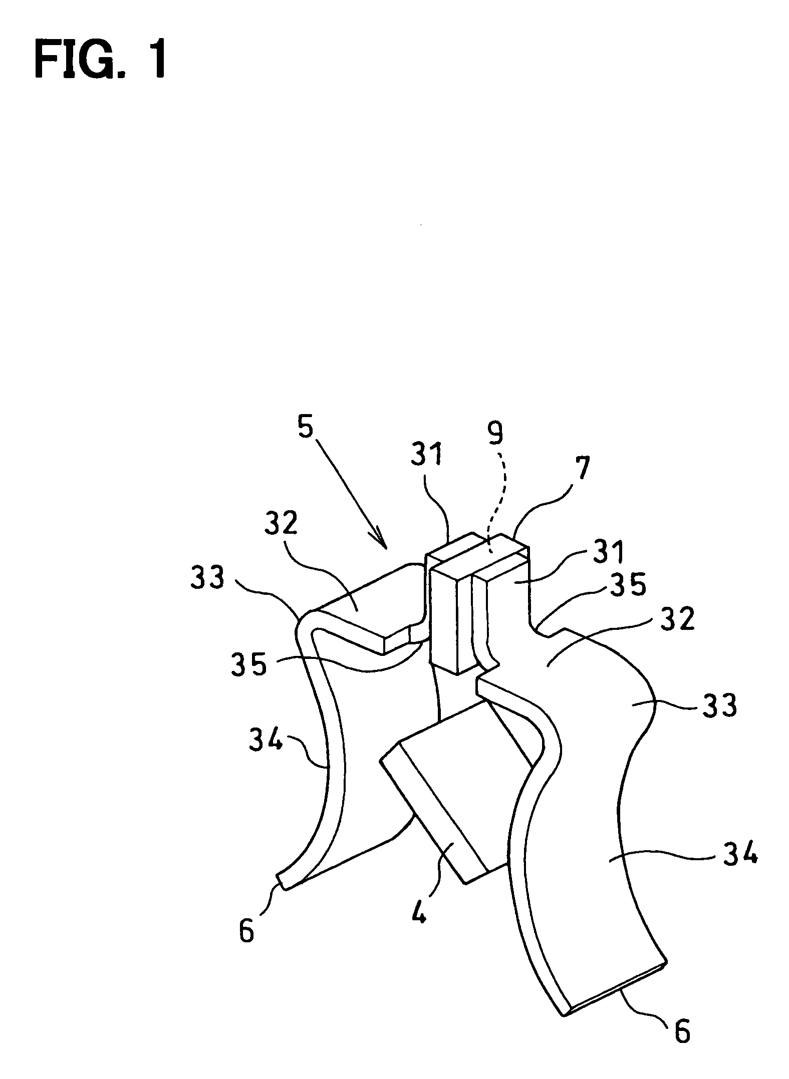
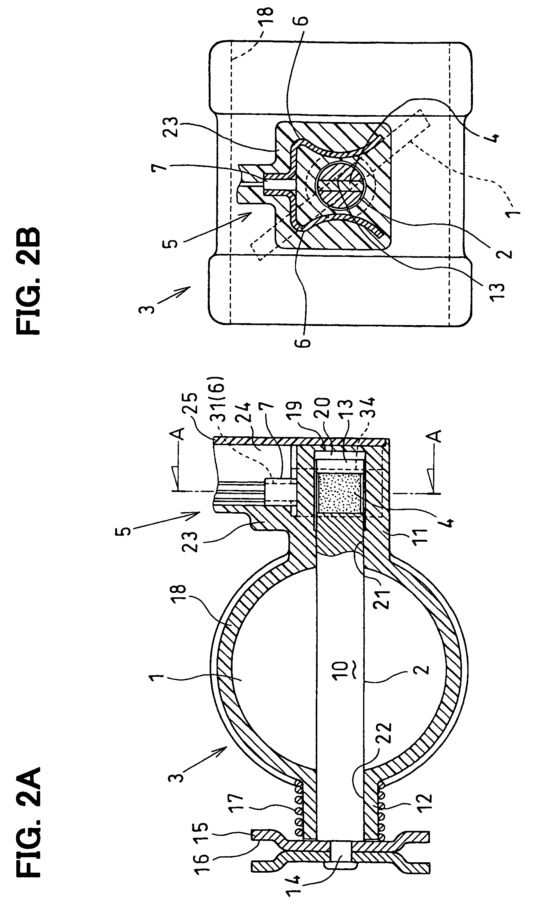
[0034]FIGS. 1 through 6 show the present invention where FIG. 1 is a view showing a throttle opening sensor and FIG. 2 is a view showing an inlet throttle device for internal combustion engine.

[0035]The inlet throttle device for internal combustion engine is a throttle device for an internal combustion engine, for controlling an engine revolution rate or an engine torque by changing the amount of intake air flowing into a combustion chamber of a cylinder of an internal combustion engine (for example, an engine for two-wheeled vehicle; hereinafter, referred to as an engine) based on the amount of operation of an accelerator by a driver (for example, the amount of operation of a throttle lever). The inlet throttle device for internal combustion engine includes a throttle valve 1 for controlling the amount of intake air sucked into the cylinder of an engine; a throttle shaft 2 cooperatively rotating with the throttle valve 1; a throttle body 3 through which the intake air toward a cyli...

second embodiment

[0064]FIG. 7 shows the present invention, illustrating an inlet throttle device for internal combustion engine.

[0065]In this embodiment, the Hall IC 7 and the lead wires of the Hall IC 7 (two output leading terminals and an electric supply terminal) are formed in the sensor retaining section 23 by insert molding with the pair of yokes 6. Since the cover plate (the sensor cover) 25 is not required in this case, the number of components and the number of assembly steps can be reduced as compared with those in the first embodiment described above. As a result, the overall cost of the rotation angle detection device can be further reduced.

[0066]In the embodiments, the accelerator lever 15 mechanically connected to the throttle lever through a wire cable is attached to one end of the throttle shaft 2 so that the rotation angle detecting device of the present invention is incorporated into the inlet throttle device for internal combustion engine, for transmitting the amount of operation o...


PUM


Abstract

A rotation angle detecting device includes a magnet (4), a magnetic substance unit (5), and a non-contact magnetic detection element (7). The magnet (4) rotates with an object to be measured and includes two ends magnetized so as to have opposite polarities. The magnetic substance unit (5) forms a predetermined air gap with the two ends of the magnet (4) and is divided into magnetic members (6) so as to provide plane symmetry with respect to a vertical plane perpendicularly crossing a rotational center axis of the magnet (4) to form a magnetic detection gap (9) by the division. The non-contact magnetic detection element (7) is provided in the magnetic detection gap (9) between the magnetic members (6) so as to output a signal corresponding to a density of a magnetic flux passing through the magnetic detection gap (9). The rotation angle of the object to be measured is detected based on the output signal from the magnetic detection element (7). The magnetic members (6) include reverse warp parts (34) so that the air gap suddenly increases when the magnet (4) rotates at a predetermined rotation angle from a state where the air gap is minimum in a direction in which the air gap increases.

Description

BACKGROUND OF THE INVENTION[0001]1. Field of the Invention[0002]The present invention relates to a rotation angle detecting device for detecting a rotation angle of an object to be measured and, more particularly, to a throttle opening detecting device for detecting a rotation angle of a throttle valve for regulating the amount of intake air sucked into a cylinder of an internal combustion engine.[0003]2. Description of the Related Art[0004]Conventionally, as a rotation angle detecting device for detecting a rotation angle of an object to be measured, for example, a throttle opening sensor (also referred to as a throttle position sensor) for detecting the degree of opening of a throttle valve (throttle opening) of an internal combustion engine has been proposed. One such example is disclosed in Japanese Patent document JP 2001-317909 A. This is, as shown in FIGS. 8A and 8B, such that a rotating shaft 101 of an object to be measured such as a throttle valve (not shown) is rotatably s...

Claims


Application Information

Patent Timeline
Patent Type & Authority Patents(United States)
IPC IPC(8): G01B7/30G01D5/14
CPCG01D5/145
Inventor NAKANO, YUJISANO, RYOFURUKAWA, AKIRAISHIDA, SHINJI
Owner DENSO CORP
Why Eureka
Try Eureka