Delay-locked loop with feedback compensation

a delay-locked loop and feedback compensation technology, applied in the direction of electrical equipment, pulse automatic control, etc., can solve the problems affecting the accuracy and performance of the dll, and achieve the effect of fast processing of current phase information, faster and more accurate phase measurements

Inactive Publication Date: 2006-07-18
MICRON TECH INC
View PDF33 Cites 43 Cited by
  • Summary
  • Abstract
  • Description
  • Claims
  • Application Information

AI Technical Summary

Benefits of technology

[0005]It is an object of this invention to provide a delay-locked loop (DLL) circuit that does not process incorrect phase information and that more quickly processes current phase information. While phase adjusted clock signals are still propagating through the circuit, feedback compensation adds or subtracts delay from the feedback path of the DLL to allow updated phase information to be input to the phase detector without having to wait for the adjusted clock signal to propagate through the entire DLL. Feedback compensation thus preferably provides faster and more accurate phase measurements in the DLL.
[0007]One or more delay models are provided in the feedback path of the DLL. When the phase detector detects a phase difference between the input and output clock signals of the DLL, it adjusts the variable delay of the DLL to minimize phase errors. At the same time, the delay model or models are applied to the inputs of the phase detector. After the adjusted signal is propagated through the DLL, the delay model or models are removed from the inputs of the phase detector. This allows the adjustment to the clock signal to be input to the phase detector quickly rather than waiting for the adjusted clock signal to propagate through the adjusted variable delay to the phase detector. This advantageously allows the DLL to correct the phase error between the input and output signals more quickly and accurately.

Problems solved by technology

This can adversely affect the accuracy and performance of the DLL.

Method used


Image

  • Delay-locked loop with feedback compensation
  • Delay-locked loop with feedback compensation
  • Delay-locked loop with feedback compensation

Examples


Embodiment Construction

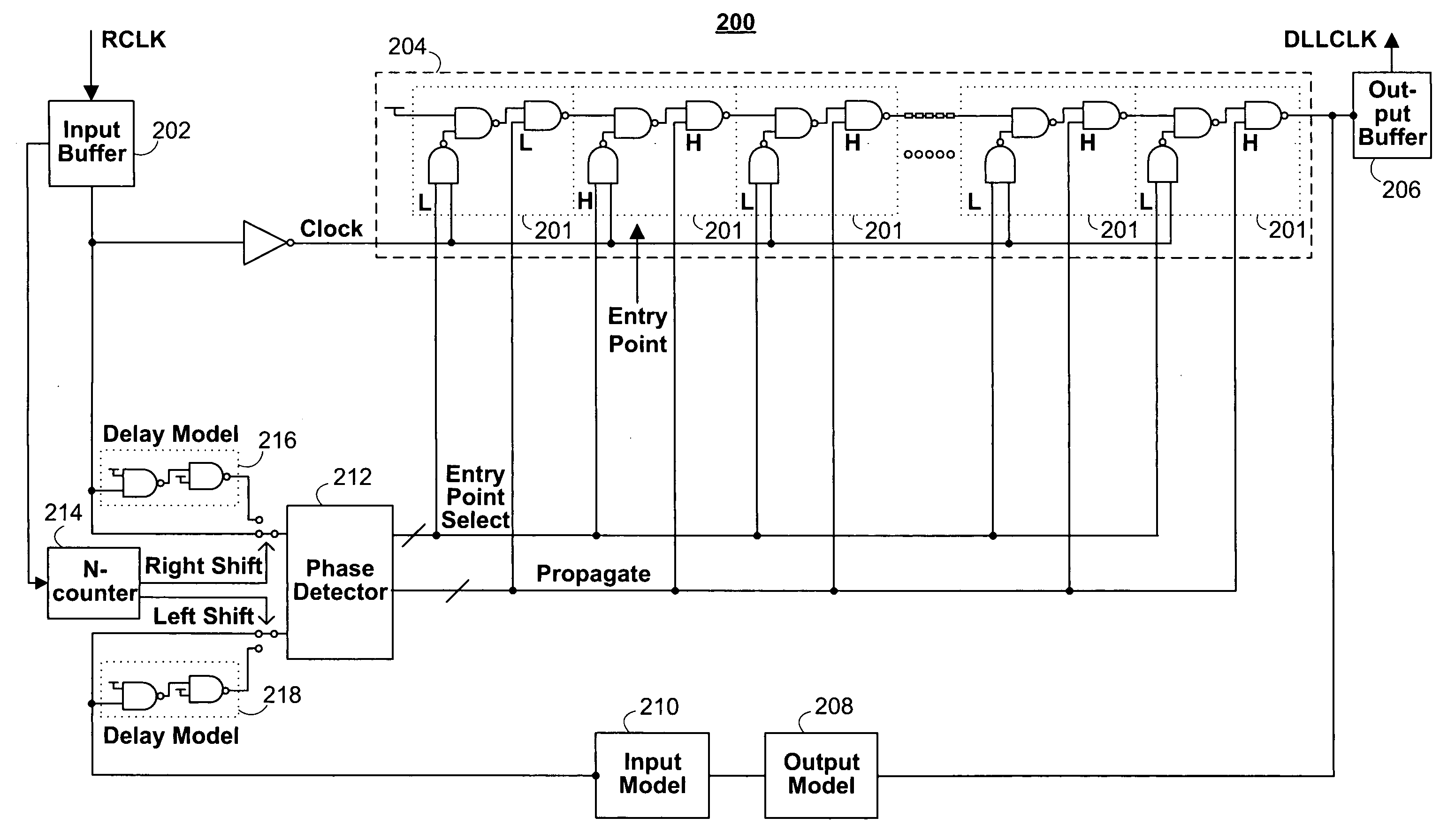
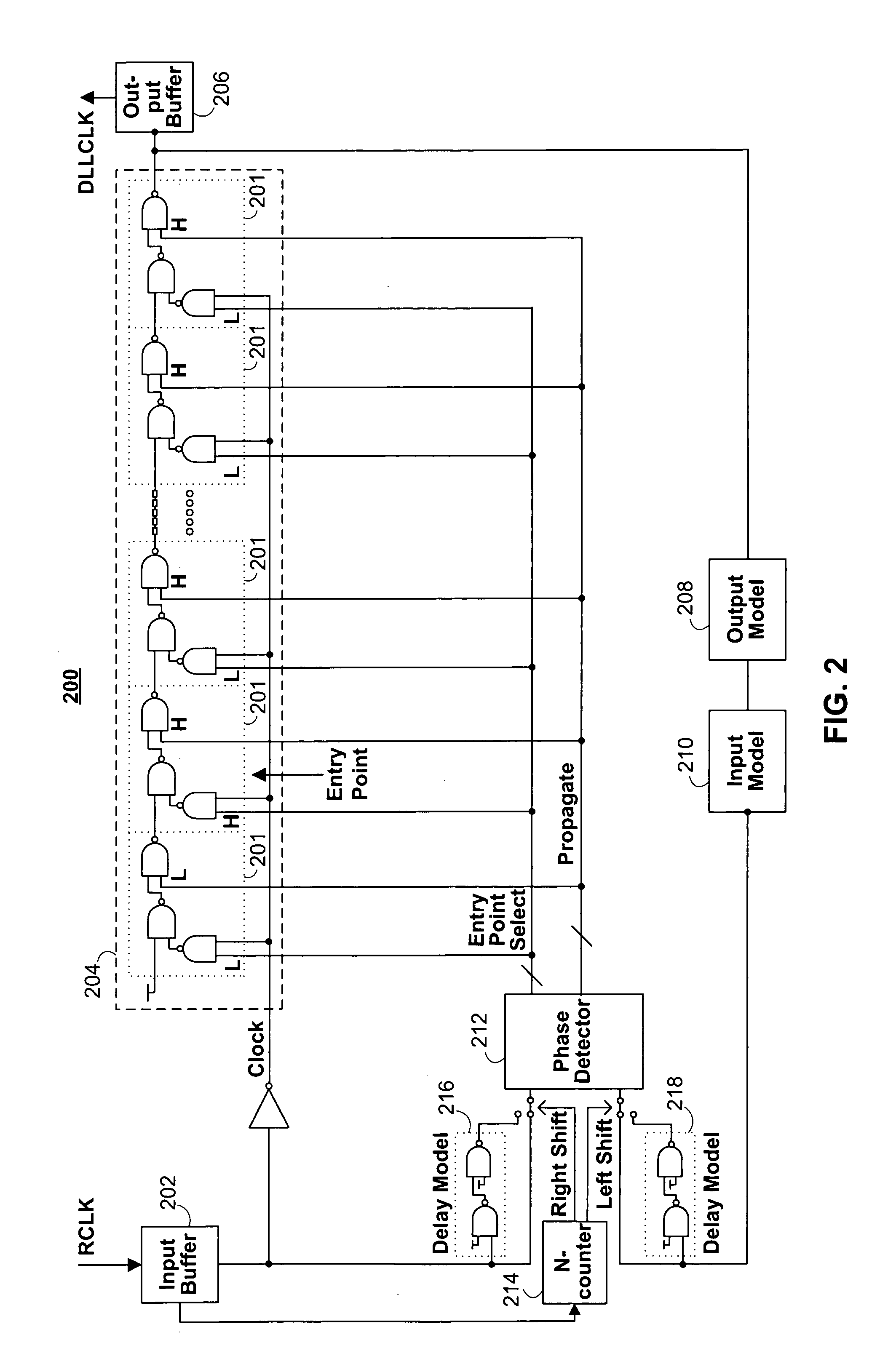
[0014]The invention provides feedback compensation in delay-locked loop (DLL) circuitry to improve the performance and accuracy of the DLL. This is accomplished by preventing the DLL from acting on old, out of date, phase information.

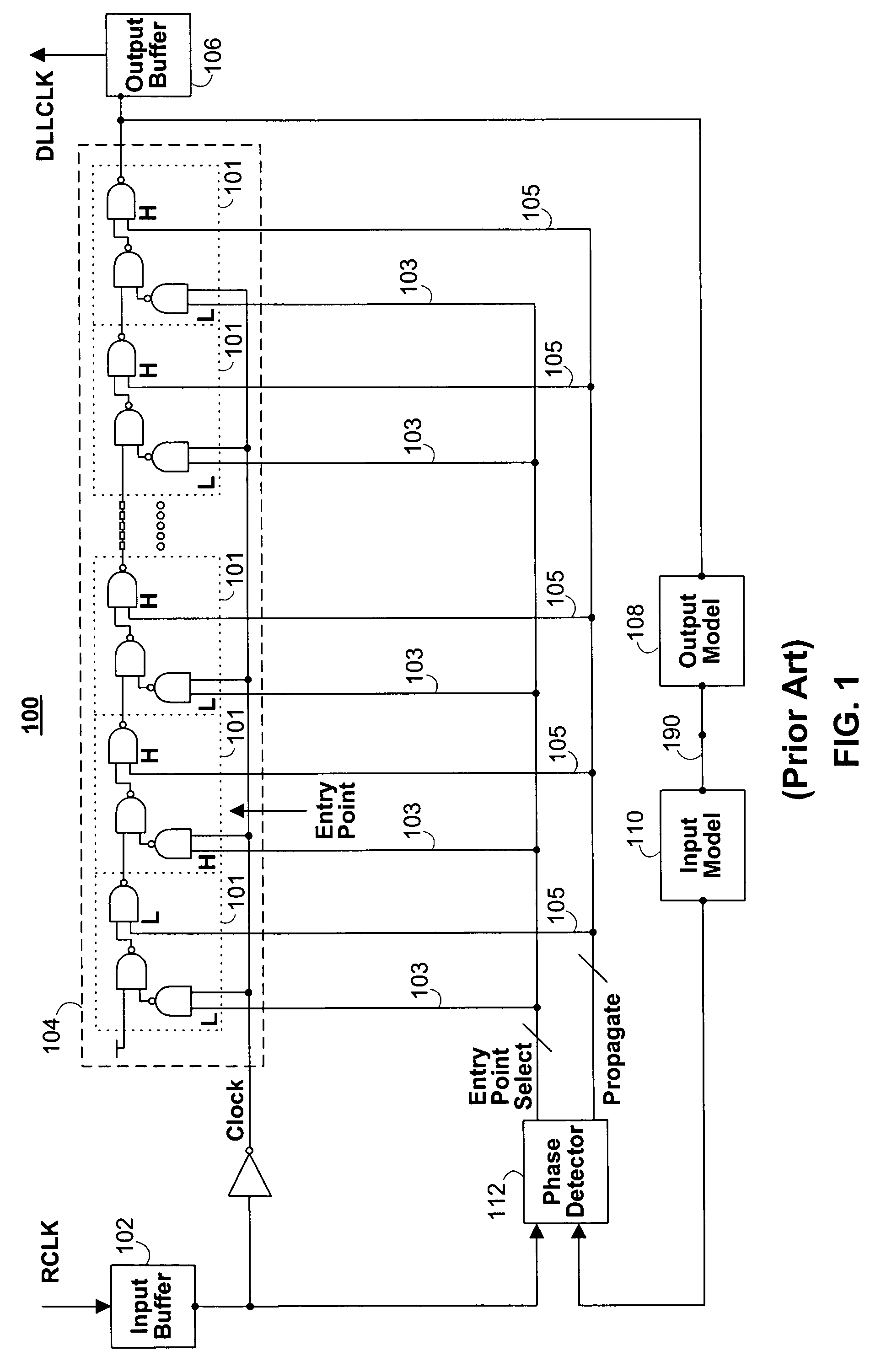
[0015]FIG. 1 shows typical DLL circuit 100. Reference clock signal RCLK is input into DLL 100 and signal DLLCLK, a delayed and synchronized version of RCLK, is output. The phase difference between RCLK and DLLCLK is ideally zero in many cases.

[0016]DLL 100 typically includes input buffer 102, variable delay line 104, output buffer 106, output delay model 108, input delay model 110, and phase detector 112. (Delay models 108 and 110 are often shown as a single delay circuit, but are shown here as two circuits for better understanding of their purpose.) Reference clock signal RCLK enters DLL 100 and passes through input buffer 102, variable delay 104, and output buffer 106 before being output as clock signal DLLCLK. Variable delay line 104 is ideally set t...


PUM


Abstract

A delay-locked loop (DLL) with feedback compensation is provided to increase the speed and accuracy of the DLL. After the variable delay line of the DLL is adjusted to minimize phase error, multiple clock cycles may be required before the adjusted signal is fed back to the phase detector. During this time, a signal replicating the adjusted signal is temporarily fed to the phase detector until the adjusted signal reaches the phase detector.

Description

BACKGROUND OF THE INVENTION[0001]This invention relates to delay-locked loop (DLL) circuits. More particularly, this invention relates to DLLs with feedback compensation.[0002]A DLL uses a variable delay line to add phase delay to an input reference clock signal before that clock signal is output from the DLL. The DLL uses a phase detector to measure the phase difference between the output of the DLL and the reference clock and to adjust the variable delay to obtain the desired phase difference, which is usually zero.[0003]As clock speeds increase, the relative length of the delay through a DLL (in clock cycles) also increases. The shorter clock period of a high speed clock becomes a smaller fraction of the total delay through a DLL. After the variable delay of the DLL is adjusted to minimize phase errors (i.e., the difference between the desired and measured phases), multiple clock periods are often required for the adjustments to propagate completely through the DLL. During this t...

Claims


Application Information

Patent Timeline
Patent Type & Authority Patents(United States)
IPC IPC(8): H03L7/06
CPCH03L7/0814H03L7/0818H03L7/087H03L7/0816
Inventor JOHNSON, GARY M
Owner MICRON TECH INC
Why Eureka
Try Eureka