Memory module cooling

a memory module and cooling technology, applied in cooling/ventilation/heating modifications, semiconductor/solid-state device details, semiconductor devices, etc., can solve the problems of limiting the dissipation of heat from that area and a large amount of heat produced in a small area, and achieve the effect of reducing the space occupied

Active Publication Date: 2006-07-18
ORACLE INT CORP
View PDF19 Cites 144 Cited by
  • Summary
  • Abstract
  • Description
  • Claims
  • Application Information

AI Technical Summary

Benefits of technology

[0012]The heatsink can dimensioned to occupy substantially a same width as the memory module on which it is mounted, for reducing space occupied by the memory module and heatsink assembly on the circuit board. The apparatus can include a socket mounted on the circuit board for receiving a plurality of memory module and heatsink assemblies side-by-side.

Problems solved by technology

This leads to a large amount of heat to being produced in a small area as well as hindering the dissipation of heat from that area.

Method used


Image

  • Memory module cooling
  • Memory module cooling
  • Memory module cooling

Examples


Embodiment Construction

[0022]Embodiments and examples are described hereafter by way of example only in the following with reference to the accompanying drawings.

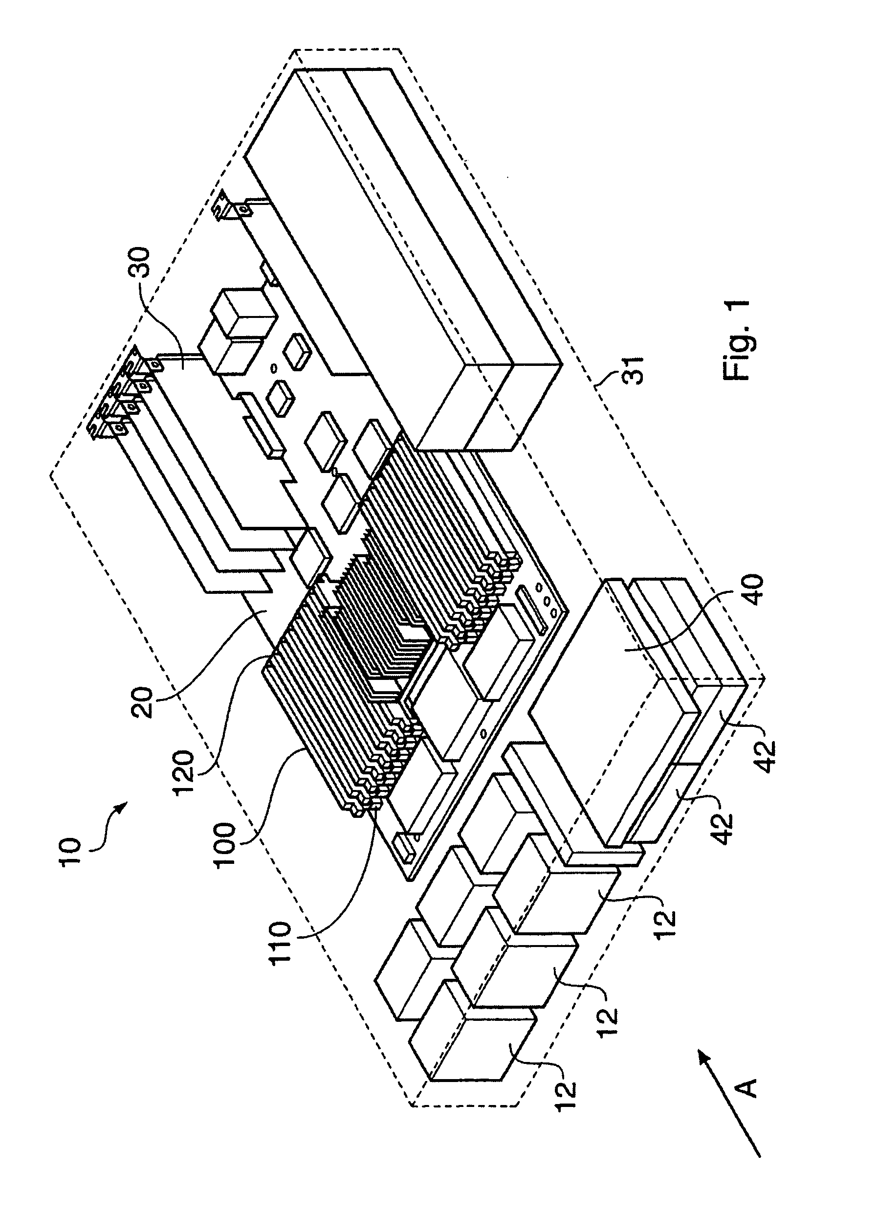
[0023]FIG. 1 illustrates an example of a computer system 10, which includes an array 100 of memory modules 120 such as Dual Inline memory Modules (DIMMs). The computer system 10 also includes a circuit board 20 upon which the array 100 is mounted. A number of further components 30 are also mounted on the circuit board 20. The circuit board 20 is provided within a housing. In FIG. 1, the housing is indicated generally by the dotted line 31, so as to avoid obscuring the view of the components housed therein.

[0024]A number of further components can also be provided within the housing. In this example, a number of hard disc drives 42 and a DVD drive 40 are provided. A number of fan units 12 are also provided.

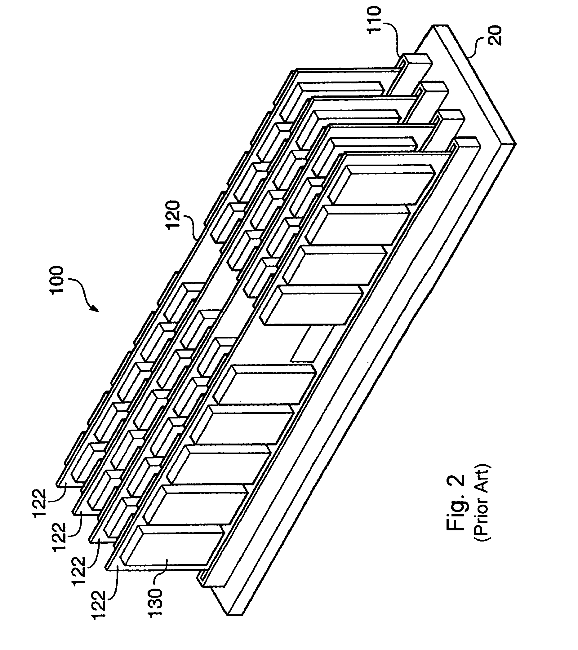
[0025]The array 100 includes a plurality of memory modules 120. In this example, each memory module 120 includes a board which is vertically mou...


PUM


Abstract

A heatsink for a memory module includes a substantially planar contact portion for forming a thermal contact with the memory module and for mounting the heatsink on the memory module. One or more formations for emitting heat are also provided, the formations for emitting heat being in thermal communication with the contact portions.

Description

BACKGROUND OF THE INVENTION[0001]The present inventions relates to providing cooling for memory modules, for example, Double Data Rate (DDR) memory modules or Dual Inline Memory Modules (DIMM).[0002]Solid state memory provided in computer systems requires cooling to avoid over heating and malfunction.[0003]With the increase in the speed of solid state memory, the amount of heat produced by such solid state memory has increased correspondingly.[0004]Furthermore, the physical density with which solid state memory is often provided in computer systems increasingly means that solid state memory components need to be placed closer together. This leads to a large amount of heat to being produced in a small area as well as hindering the dissipation of heat from that area.[0005]The present invention aims to solve at least some of the problems indicated above.SUMMARY OF THE INVENTION[0006]Aspects of the invention are defined in the accompanying independent and dependent claims.[0007]Accordin...

Claims


Application Information

Patent Timeline
Patent Type & Authority Patents(United States)
IPC IPC(8): H05K7/20H01L23/367
CPCH01L23/3672H01L2924/0002H01L2924/00
Inventor GATES, WILLIAM GEORGEHARRIS, RICHARD JOHNWRYCRAFT, SEAN CONOR
Owner ORACLE INT CORP
Why Eureka
Try Eureka