
Hearing aid device wearable in the ear or hearing aid device having an otoplastic wearable in the ear

Active Publication Date: 2006-07-18
SIVANTOS PTE LTD
View PDF9 Cites 39 Cited by
  • Summary
  • Abstract
  • Description
  • Claims
  • Application Information

AI Technical Summary

Benefits of technology

[0007]An object of the present invention is to provide an aeration channel in a hearing aid device wearable in the ear or a hearing aid device having an otoplastic wearable in the ear such that a good ventilation effect is achieved and the risk of feedback through the aeration channel is minimized at the same time.
[0010]Proceeding from this exemplary embodiment, the decisive, moved medium mass of the ventilation opening can be reduced via a targeted variation of the ventilation channel. A diminished radiation impedance takes effect due to a modified cross-section at the end of the aeration channel given an aeration channel that is otherwise unmodified. The advantage compared to the traditional ventilation systems is that the diminishing acoustic emission goes into space. This yields a clearly improved stability of the hearing aids in practice and, second, allows the employment of an aeration channel having an enlarged cross-sectional area in all sub-regions compared to a traditional hearing aid device or to a traditional otoplastic upon retention of the stability conditions.
[0013]One embodiment of the invention provides that, particularly given loner aeration channels, acoustic filter elements are arranged in an aeration channel. Longer aeration channels cause the occurrence of line resonances at which the acoustic conductivity of the aeration channel is maximized. The occurrence of resonance effects is prevented by the acoustic filter elements. The filter elements can, for example, be fashioned as discontinuities in cross-section or as acoustic damping elements introduced into the aeration channel.

Problems solved by technology

However, the aeration channel represents an acoustic bypass to the signal path via the input transducer, the signal processing unit, and the output transducer of the hearing aid device, which can reduce functions of the hearing aid device such as a particular directional effect or an unwanted noise reduction, making these functions ineffective, particularly in a loud acoustic situation.
Furthermore, feedback between the output transducer and the input transducer can occur via the aeration channel, particularly in acoustic situations with a low input signal level and a high gain of the hearing aid device caused by dynamic compression.

Method used


Image

  • Hearing aid device wearable in the ear or hearing aid device having an otoplastic wearable in the ear
  • Hearing aid device wearable in the ear or hearing aid device having an otoplastic wearable in the ear

Examples


Embodiment Construction

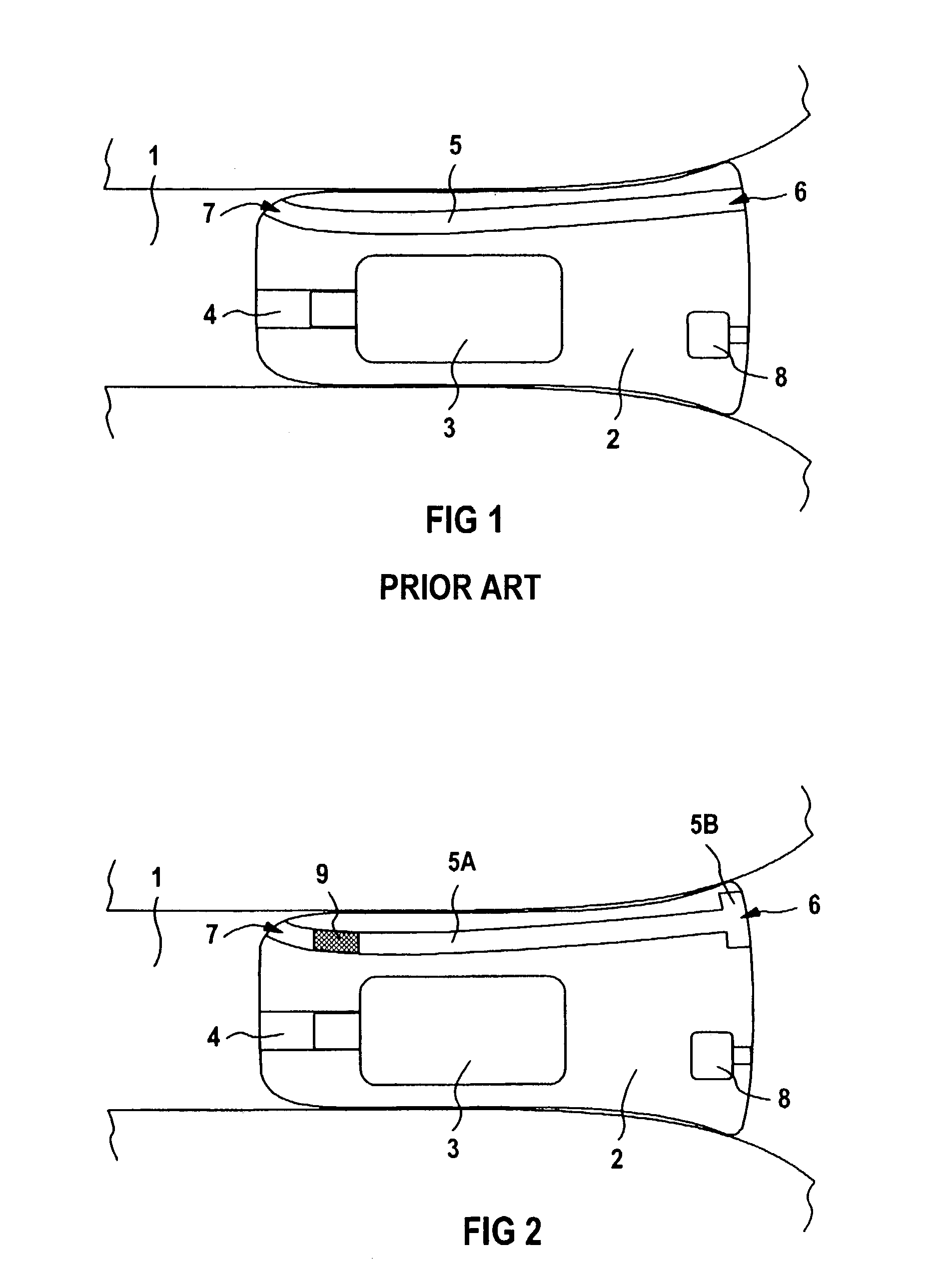
[0017]In a schematic, highly simplified presentation, FIG. 1 shows a hearing aid device 2 arranged in the auditory canal 1 of a hearing aid user. An acoustic signal is supplied to the ear of the hearing aid user via, on the one hand, a microphone 8, a signal processing unit (not shown) and an earphone with allocated earphone channel 4 and, on the other hand, via the aeration channel 5. The aeration channel 5 thus represents a bypass for the electro-acoustic signal path through the hearing aid device 2.

[0018]In specific acoustic situations, for example, given slight acoustic amplification of the hearing aid device due to a loud sound environment, this bypass is dominant over the signal path through the hearing aid device. This can limit the effectiveness of specific functions or aspects of the hearing aid device such as, for example, a desired directional effect or a reduction of unwanted noise. Over and above this, feedbacks between the earphone 3 and the microphone 8 can also occur...


PUM


Abstract

Acoustic feedbacks can be caused by the aeration channel (5) that is present in hearing aid devices (2) wearable in the ear or hearing aid devices having an otoplastic wearable in the ear. In order to avoid this, it is provided that the aeration channel be subdivided into at least a first and a second sub-region, whereby the sub-region (5A) that is proximal when the hearing aid device (2) is worn or when the otoplastic is worn comprises a small cross-sectional area and a great length compared to the distal, second sub-region (5B).

Description

BACKGROUND OF THE INVENTION[0001]1. Field of the Invention[0002]The invention is directed to a hearing aid device wearable in the ear or hearing aid device having an otoplastic wearable in the ear, comprising an aeration channel.[0003]2. Description of the Related Art[0004]The aeration channel (“ventilation bore” or “vent”) of a hearing aid device wearable in the ear or of a hearing aid device having an otoplastic wearable in the ear serves for ventilating the ear canal, for atmospheric pressure compensation, or for reducing the closure effect (occlusion effect). It is desirable to provide an aeration channel having an optimally large cross-section.[0005]However, the aeration channel represents an acoustic bypass to the signal path via the input transducer, the signal processing unit, and the output transducer of the hearing aid device, which can reduce functions of the hearing aid device such as a particular directional effect or an unwanted noise reduction, making these functions ...

Claims


Application Information

Patent Timeline
IPC IPC(8): H04R25/00
CPCH04R25/652H04R2460/11
Inventor NIEDERDR NK, TORSTEN
Owner SIVANTOS PTE LTD
Features
  • Generate Ideas
  • Intellectual Property
  • Life Sciences
  • Materials
  • Tech Scout
  • Unparalleled Data Quality
  • Higher Quality Content
  • 60% Fewer Hallucinations
Learn More