
High-resolution intelligent rotor machine diagnostic system and method

a diagnostic system and intelligent technology, applied in the field of intelligent rotor machine diagnostic system and method, can solve problems such as the inability to achieve an effective diagnosis

Inactive Publication Date: 2006-07-18
NAT CHIAO TUNG UNIV
View PDF6 Cites 2 Cited by
  • Summary
  • Abstract
  • Description
  • Claims
  • Application Information

AI Technical Summary

Benefits of technology

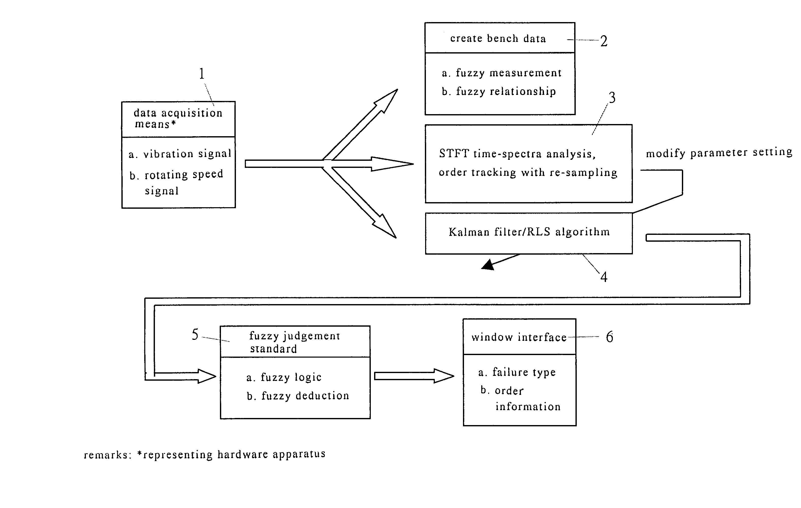
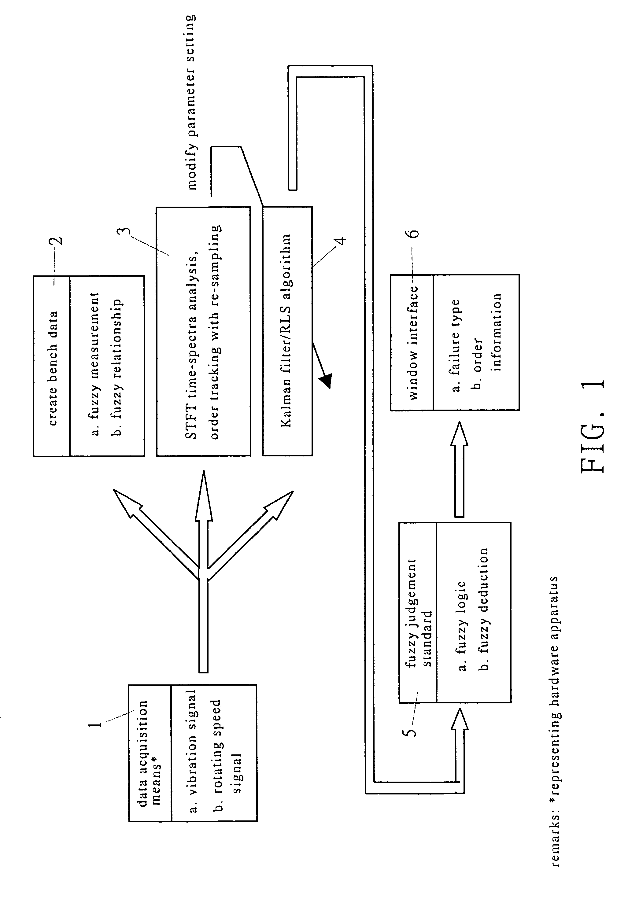
[0031]Now refer to FIG. 1, it is a flow chart showing the method of performing high-resolution order analysis / diagnosis on rotor. To conduct such method, the present invention provides a system comprises: a data acquisition means 1, for measuring the vibration signal and tacho signal of a rotor; a bench data setup means 2, for creating fundamental data of the bench in accordance with measured vibration signal and tacho signal of the rotor as well as the characteristic of the bench itself; a STFT time-spectra analysis / re-sampled order tracking means 3, for conducting a short-time Fourier transformed (STFT) time-spectra analysis and re-sampled order tracking; a Kalman filter or RLS algorithmic means 4, including a Kalman filter and a RLS algorithm; (e) a fuzzy diagnosis means 5, including a fuzzy logic unit and a fuzzy deduction unit to achieve the fuzzy diagnosis standard; and (f) a window interface (e.g., GUI), for outputting a diagnosis of failure type and order information. While by repeatedly conducting those diagnosis steps, it is then possible to achieve the object of present invention.

Problems solved by technology

However, the prior technique has the following disadvantage: (1) limitation applied to the resolution and status analyzing conducted through a conventional method of order analysis based on Fourier transform; (2) current order analysis based on the Kalman filter is conducted under off-line condition; (3) such diagnosis technique is conducted in accordance with a time- or frequency-based alarm value therefore it is impossible to achieve an effective diagnosis on complicated failure states; and (4) such technique relies completely on an highly experienced technician to conduct a post-result judgment on the process.

Method used


Image

  • High-resolution intelligent rotor machine diagnostic system and method
  • High-resolution intelligent rotor machine diagnostic system and method
  • High-resolution intelligent rotor machine diagnostic system and method

Examples


Embodiment Construction

[0013]In the following context, the detailed description on the preferred embodiment of present invention will be given with reference to the attached figures, in which similar parts are denoted with same reference numbers.

[0014]The object of present invention is to provide a smart system and method of performing high-resolution frequency order analysis and diagnosis on rotor apparatus. The rotor apparatus generally refers to a rotary mechanical system such as car engine, rotor set of power generator, machining bench (e.g., lathe), power system of ship and etc.

[0015]The high-resolution frequency order analysis / diagnosis smart system of present invention is constituted of several means with different function as follows:

[0016](a) a data acquisition means 1, for measuring the vibration signal and tacho signal of a rotor; in one embodiment, the data acquisition means comprises components such as a accelerating gauge for measuring the vibration signal of a rotor in rotary apparatus, a f...


PUM


Abstract

The present invention relates to a smart system and method of performing high-resolution frequency order analysis / diagnosis on rotor, in which such system is characterized in that capable of performing order analysis via a Kalman filter or a RLS (Recursive Least Square) algorithm while determining the failure status based on the Fuzzy theory. The smart system of present invention comprises a data acquisition means, a bench data setup means, a STFT time-spectra analysis / re-sampled order tracking means, a Kalman filter or RLS algorithmic means, a fuzzy diagnosis means and a window interface (e.g., GUI) while repeatedly making use the functions of those means so as to achieve the real-time diagnosis on rotor.

Description

FIELD OF THE INVENTION[0001]The present invention relates to a smart system and method of performing high-resolution frequency order analysis / diagnosis on rotor, characterized in that such system performs a real-time on-line frequency order diagnosis via a STFT (Short Time Fourier Transform) time-spectra analysis / re-sampled order tracking means, a Kalman filter or RLS algorithmic means, and a fuzzy diagnosis means.RELATED ART[0002]In the industrialization countries, there is relative high need on mechanical maintenance and diagnosis. Conventional mechanical maintenances are performed largely through failure restore, time-based maintenance and predictive maintenance. According to the result of analysis, performing the predictive maintenance provides the minimum loss in the system performance while increasing the yield and reducing the cost of production. As for the diagnosis technique, the conventional method relies on the instinct of a skilled technician to provide a predictive main...

Claims


Application Information

Patent Timeline
Patent Type & Authority Patents(United States)
IPC IPC(8): G06F19/00G05B23/02
CPCG05B23/0254G01M7/00G01H1/003
Inventor BAI, MING-SIANHUNG, MING-HUNGHUANG, JIA-MINSU, FU-CHENG
Owner NAT CHIAO TUNG UNIV
Learn More