Apparatus and methods for double ended processing

a technology of double-ended processing and apparatus, applied in the field of material processing, can solve the problems of occupying too much space, wasting time, and wasting money, and may not be cost effective to buy separate positioning assemblies for multiple machines

Active Publication Date: 2006-07-25
PRECISION AUTOMATION
View PDF55 Cites 23 Cited by
  • Summary
  • Abstract
  • Description
  • Claims
  • Application Information

AI Technical Summary

Benefits of technology

[0007]In another aspect of the invention a method is carried out. An apparatus includes a pusher positioned between first and second machines along a processing path. The pusher is operable to push work pieces alternately in opposite directions toward both machines. The pusher is controlled by a computer. An interlock is provided for each machine to prevent operation of the respective machine when the pusher is moving. A machine is first selected for use. The interlock for the machine is activated. A work piece such a piece of

Problems solved by technology

However, buying separate positioning assemblies for multiple machines may not be co

Method used


Image

  • Apparatus and methods for double ended processing
  • Apparatus and methods for double ended processing
  • Apparatus and methods for double ended processing

Examples


Embodiment Construction

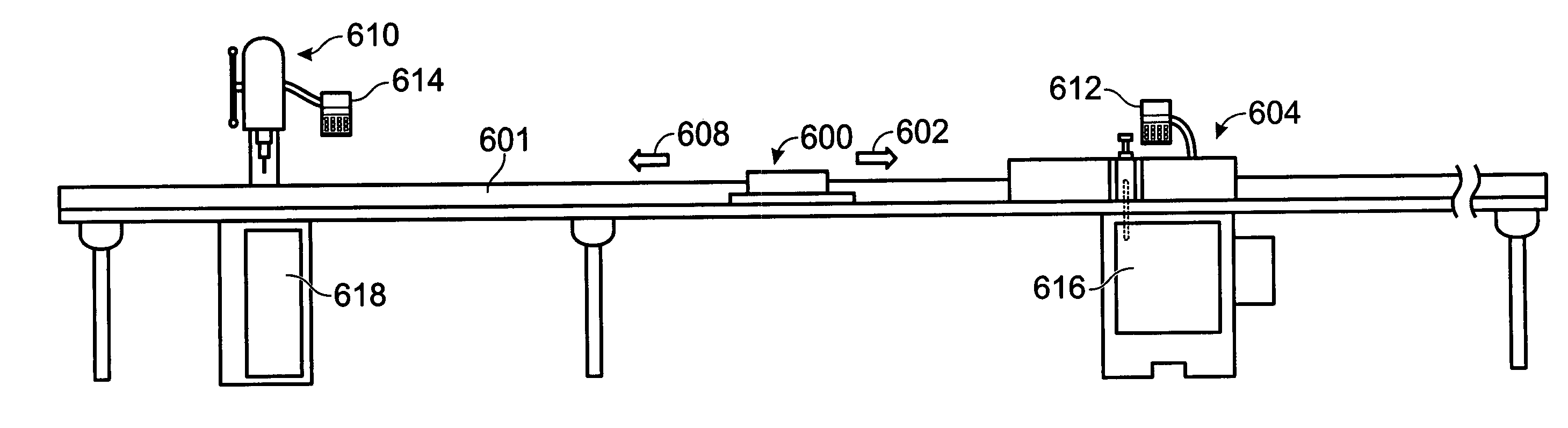
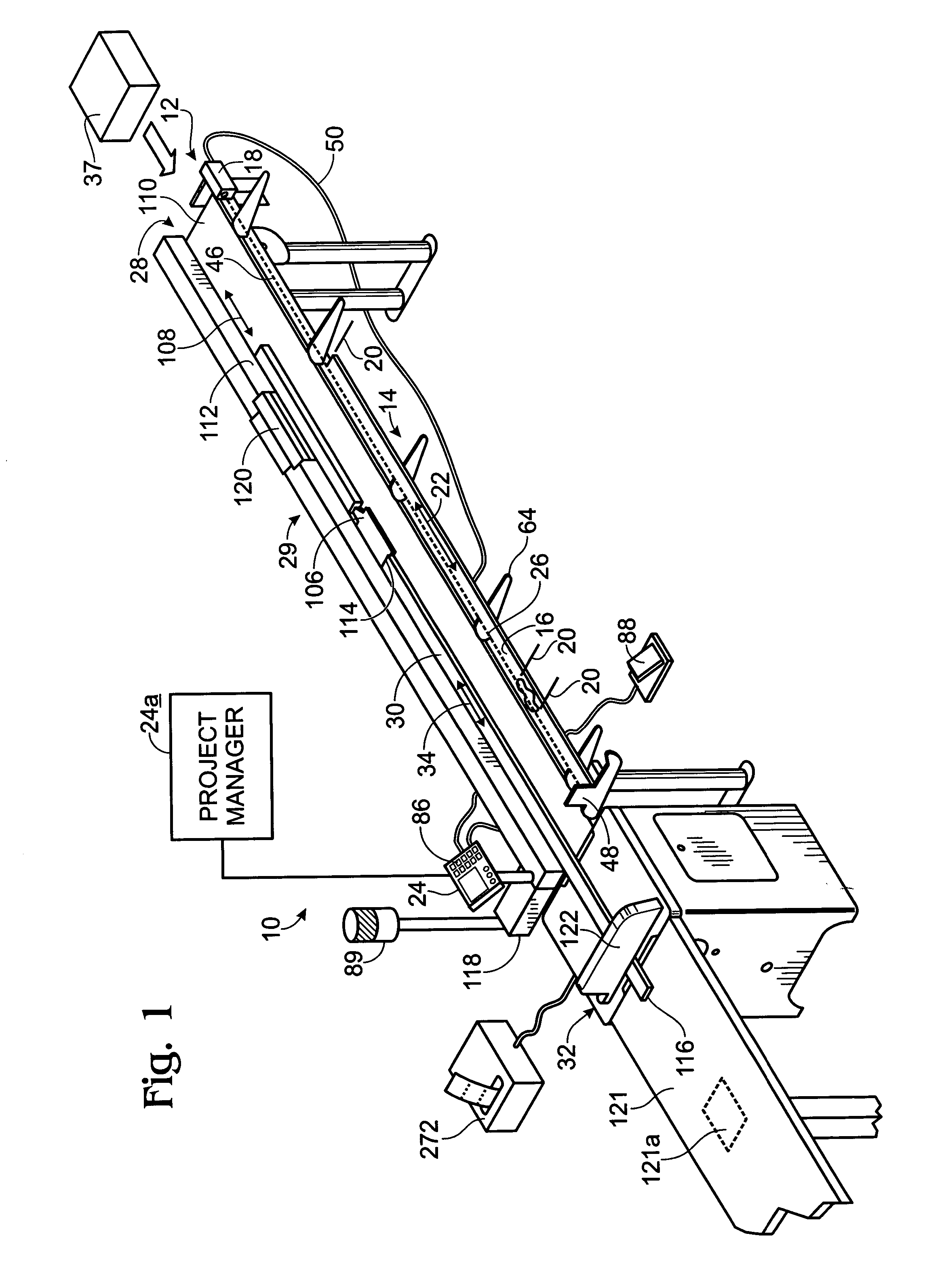
[0017]An example of an automated processing system constructed in accordance with the present invention is shown generally at 10 in FIG. 1. System 10 includes a marking assembly 12 positioned along a front portion of the system. Marking assembly 12 includes a marking station 14 to orient an article or material 16 relative to an optical measuring device 18. The article may be a wood product, metal, plastic, ceramic, and / or the like. The article may have any suitable shape and size, and may be elongate to define a long axis, which also may be a processing axis.

[0018]Feature locations 20 along a processing axis 22 of material 16 may be input by a user to the optical measuring device 18, which communicates the feature locations to a controller 24. Another computer 24a may be used remotely from controller 24 to store, edit, combine, or modify cut lists prior to downloading one or more cut lists to controller 24. Marking assembly 12 allows a user to virtually mark feature locations 20 of ...


PUM


Abstract

System, including apparatus and method, involves processing materials in opposite directions between two machines along a processing path.

Description

CROSS-REFERENCE TO RELATED APPLICATIONS[0001]This application claims priority under 35 U.S.C. § 119 and applicable foreign and international law of U.S. Provisional Patent Applications Ser. Nos. 60 / 405,067 and 60 / 405,069 filed Aug. 20, 2002, each of which is hereby incorporated by reference in its entirety.[0002]This application incorporates by reference in its entirety the following U.S. patent applications and patents: U.S. patent application Ser. No. 09 / 578,806 filed May 24, 2000 entitled “Automated Fence Control Coupling System,” now abandoned; U.S. patent application Ser. No. 09 / 861,231 filed May 17, 2001 entitled “System and Method of Marking Materials for Automated Processing,” now U.S. Pat. No. 6,631,006; U.S. patent application Ser. No. 10 / 104,492 filed Mar. 22, 2002 entitled “Automated Fence Control Coupling System,” now abandoned; U.S. Provisional Patent Application Ser. No. 60 / 405,068 filed Aug. 20, 2002 entitled “Process Management System and Method”; and U.S. Pat. Nos....

Claims


Application Information

Patent Timeline
IPC IPC(8): B23P23/00B23D47/04B23D59/00B27B31/00B27C9/04B27M1/08
CPCB23D47/04B23D59/008B27B31/00B27C9/04B27M1/08B23D59/001Y10T29/5124Y10T408/3809Y10T29/5146Y10T29/49778Y10T408/173Y10T408/10Y10T29/5107Y10T29/5148Y10T29/5136Y10T83/4491Y10T83/155
Inventor SAWYER, PHILIP P.MORGAN, DAVID A.LEE, DAVID
Owner PRECISION AUTOMATION
Why Eureka
Try Eureka