Controlled cooking system

a technology of cooking system and control panel, which is applied in the direction of cooking vessels, roasting apparatus, instruments, etc., can solve the problems that the preparation and cooking of meals in the oven or rotisserie is not without inherent problems, and achieve the effect of inherent temperature sensitivity

Inactive Publication Date: 2006-07-25
FRANKEL DAVID
View PDF6 Cites 90 Cited by
  • Summary
  • Abstract
  • Description
  • Claims
  • Application Information

AI Technical Summary

Benefits of technology

[0005]The controlled cooking system (CCS) is designed to automatically alert a cook that food being cooked in an oven or a rotisserie is sufficiently cooked. The system can be designed to function with either an electric oven, a gas oven or a rotisserie. An internal cooking temperature measurements sensor consisting of a Radio Frequency Identification (RFID) tag with or without anti-collision capability is utilized to measure th...

Problems solved by technology

The ability to prepare and cook a meal in an oven or rotisserie is not without inherent proble...

Method used


Image

  • Controlled cooking system
  • Controlled cooking system
  • Controlled cooking system

Examples


second embodiment

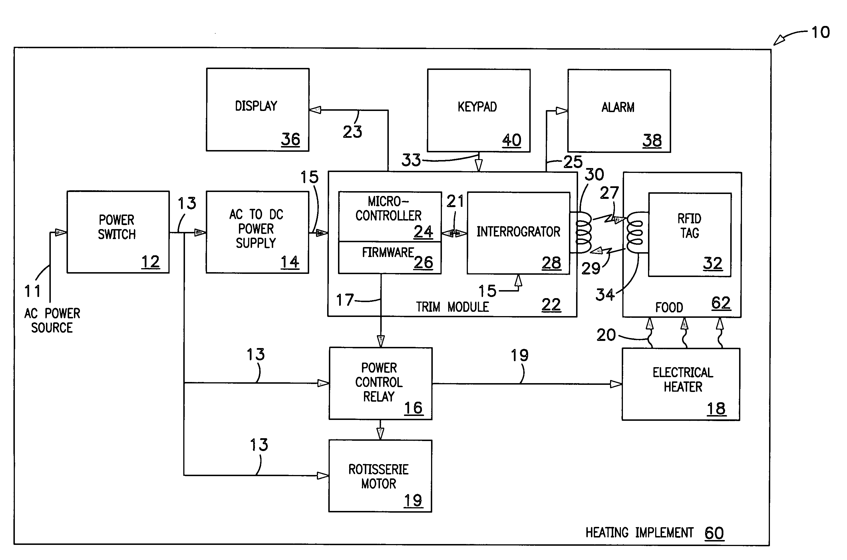
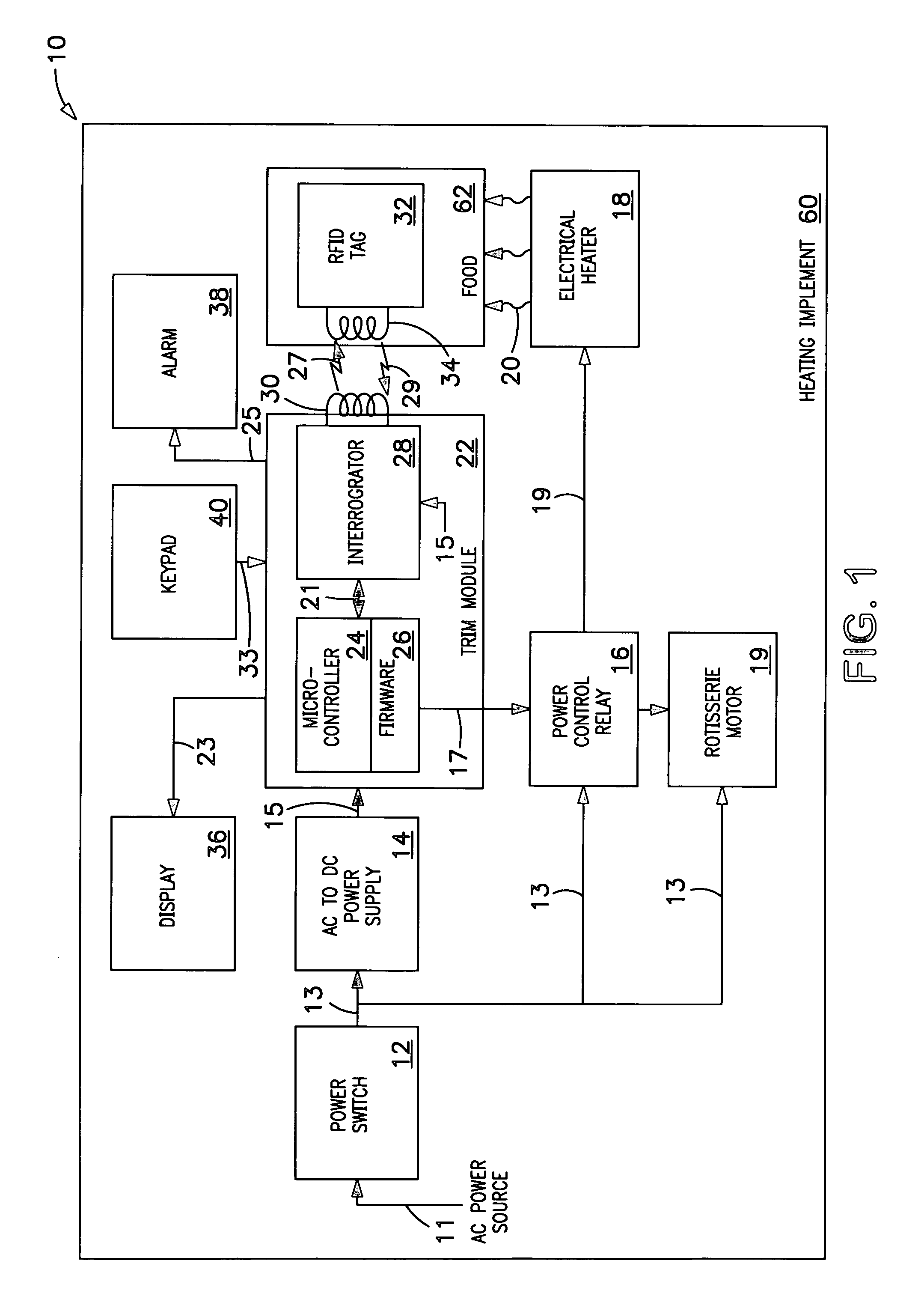
[0020]The best mode for carrying out the invention is presented in terms of a preferred embodiment for a controlled cooking system (hereinafter “CCS 10”). The preferred embodiment of the CCS 10 is described in terms of an all-electric CCS 10, as shown in FIG. 1, and a second embodiment that uses gas heat in combination with electrically operated components, as shown in FIG. 2. The term “food 62” as referred to herein is intended to include beef, poultry, fish, bread, cakes and other cooked or baked foods.

[0021]The all-electric CCS 10, as shown in FIG. 1, is comprised of a power control switch 12, an a-c to d-c power supply 14, a power control relay 16, an electric heater 18, a microprocessor 24, an interrogator 28, a passive Radio Frequency Identification (RFID) tag 32 having an internal temperature sensor, a display 36, an alarm 38, and a keypad 40.

[0022]The power switch 12 has an input 11 that is connected to a utility power source that can consist of either 120-volts a-c, 220-vol...

first embodiment

[0031]The final component described for the first embodiment is the keypad 40 which is connected to the third input of the microprocessor 24, via the keypad signal 33, as shown in FIG. 1. The keypad is designed to input various selectable foods by name as programmed in the microprocessor 24.

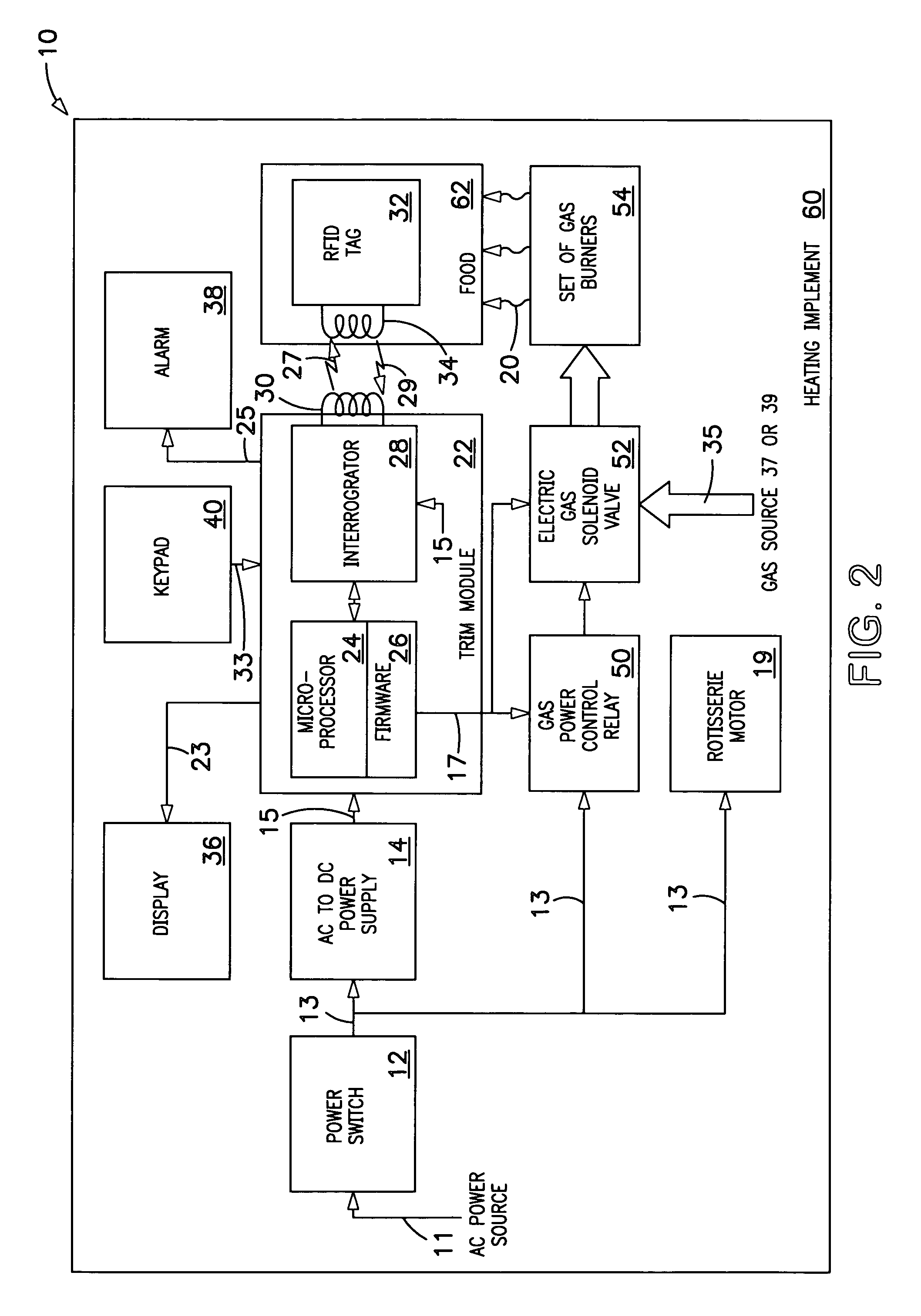
[0032]The second embodiment of the CCS 10 operates with a combination electric-gas oven, as shown in FIG. 2, that utilizes the identical electronic components used in the first embodiment but differs in the non-electric components namely, a gas-power control relay 50, an electric-gas solenoid valve 52, and a set of gas burners 54.

[0033]The electric-gas solenoid valve 52 has a gas input that is connected to a gas source provided by either a utility gas source 37 or a portable gas source 39. The gas power control relay 50, in combination with the microprocessor 24, controls the application of the gas source 37,39 to the electric-gas solenoid valve 52. The valve 52, in turn, controls the flow of gas...


PUM


Abstract

A controlled cooking system (CCS) that monitors, measures, and controls the internal temperature of foods placed in an oven having a Radio Frequency Identification (RFID) antenna(s), a transmitter/receiver/interrogator/reader/microprocessor (TRIRM) module and an RFID tag with built-in temperature sensor. The RFID tag is buried in the food being cooked and is energized and enabled by an RF signal of pre-determined frequency. The tag output is an RF “backscatter signal” having encoded temperature data indicative of the internal temperature of the food that the tag is buried in. The backscatter signal is received and decoded by the antenna(s) and the TRIRM module incorporating a programmed cooking/baking temperatures for various foods. If the decoded temperature is below a user-set temperature, the TRIRM module allows the oven to remain on. Conversely, if the decoded temperature is at or exceeds the user-set temperature, the TRIRM module shuts off the oven and produces a signal that activates an alarm indicating that the cooking has been terminated.

Description

[0001]This application claims priority of Provisional Patent Application No. 60 / 416,120 dated Oct. 4, 2002.TECHNICAL FIELD[0002]The invention pertains to the general field of food-cooking ovens and more particularly to a controlled cooking system that monitors, measures and controls the internal temperature of food(s) being cooked or baked. The system automatically shuts off the oven and sounds an alarm when a preset internal temperature has been attained, thus indicating that the cooking cycle has been completed.BACKGROUND ART[0003]The ability to prepare and cook a meal in an oven or rotisserie is not without inherent problems. One such problem is the ability to cook a meal so that the food is not undercooked or overcooked. Because a cook is often busy attending to other cooking duties, the food may not be removed from the oven or rotisserie at an optimum time to assure that the meal is properly cooked. The instant invention is designed to easily solve the cooking temperature and t...

Claims


Application Information

Patent Timeline
IPC IPC(8): A47J37/00A47J37/04
CPCA47J37/041A47J27/62A47J36/32
Inventor FRANKEL, DAVID
Owner FRANKEL DAVID
Why Eureka
Try Eureka