Hollow jewelry ring design

a hollow and jewelry technology, applied in the field of hollow jewelry ring design, can solve the problems of not teaching the unable to achieve proper alignment of inserts and prevent, and less than desirable use of soluble wax core inserts

Inactive Publication Date: 2006-07-25
QUALITY CASTING
View PDF4 Cites 3 Cited by
  • Summary
  • Abstract
  • Description
  • Claims
  • Application Information

AI Technical Summary

Benefits of technology

[0009]Because the ring model includes a plate with extending spokes supported along the internal perimeter of the shank, it is possible to produce a core insert of a similar configuration, thereby enabling the production of a ring or other jewelry article which is bored out or hollowed within the shank thereof.

Problems solved by technology

In the prior art, the use of soluble wax core inserts has been less than desirable.
In the first place, there have been difficulties in achieving proper alignment of the insert and in preventing random movement or shifting of the insert during waxing or casting.
In addition, the prior art has failed to teach the use of a soluble wax core insert such that a hollow or bored out space is defined within the ring which extends virtually along the entire arcuate length thereof.
Moreover, in the prior art U.S. Pat. No. 5,718,278 to Baum, it is stated that it is not possible to produce a ring having an inner round radius design utilizing a vertically oriented mold configuration.
However, the Baum process which utilizes a horizontally oriented mold configuration is less than desirable since it is not able to produce a ring which is hollowed or bored out to an arcuate content of 200° and up to or approaching 360°.

Method used


Image

  • Hollow jewelry ring design
  • Hollow jewelry ring design
  • Hollow jewelry ring design

Examples


Embodiment Construction

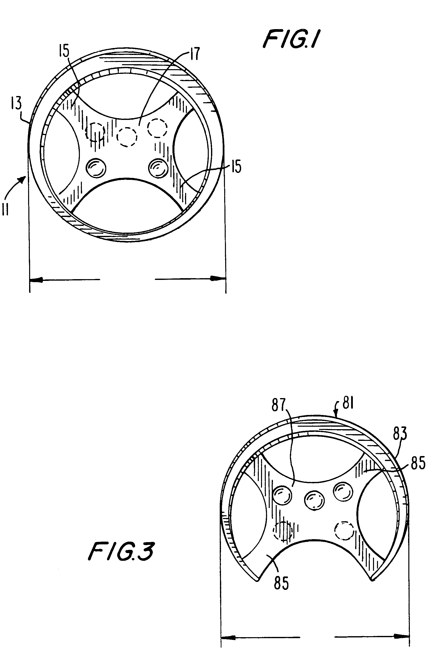
[0038]Referring first to FIG. 1, a metal ring model which is used in producing a ring mold is generally indicated at 11. Metal ring model 11 consists of a shank 13, an internally extending plate element 17 supported along the internal perimeter of shank 13 and a plurality of extending fingers or spokes 15. Metal ring model 11 has an external shape identical to the jewelry ring that is to be produced in accordance with the invention. Shank 11 has a flat finger facing surface with rounded or beveled edges. Metal plate 17, including fingers 15, are provided for enabling production of a core insert with a supporting plate and for thereby defining the extent to which the shank of the ring to be produced is hollowed or bored out, as described. Metal ring model 11 is used, as is well known in the art, to then prepare a vertically oriented mold thereof, as shown in FIG. 2.

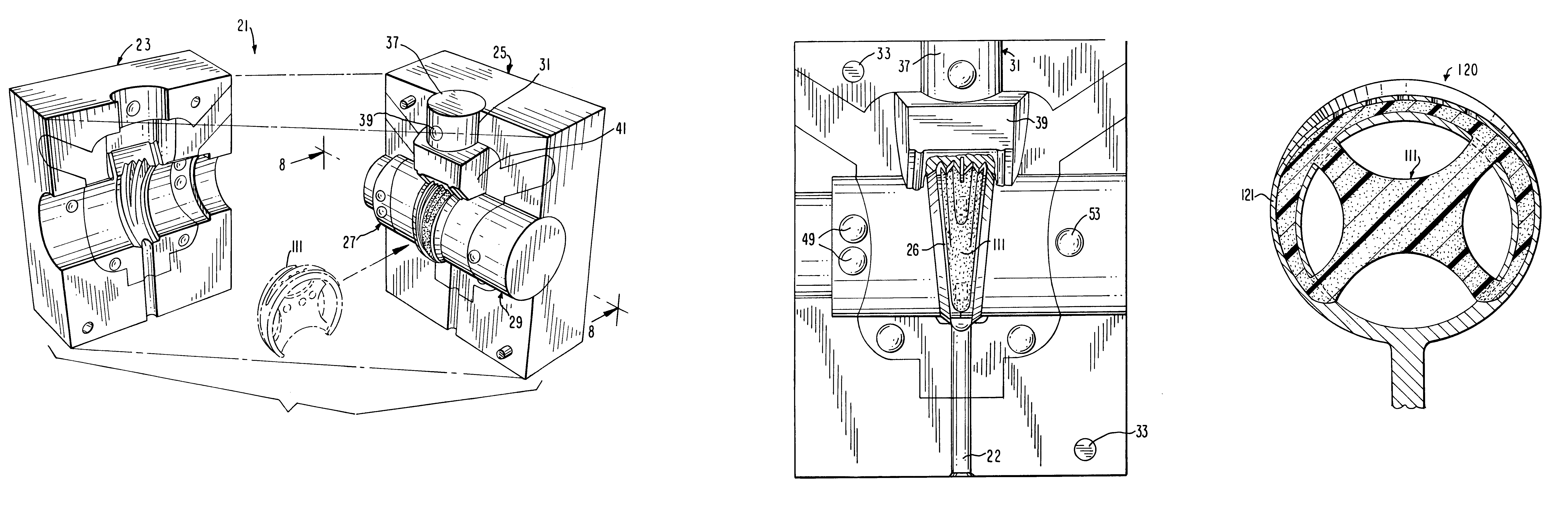
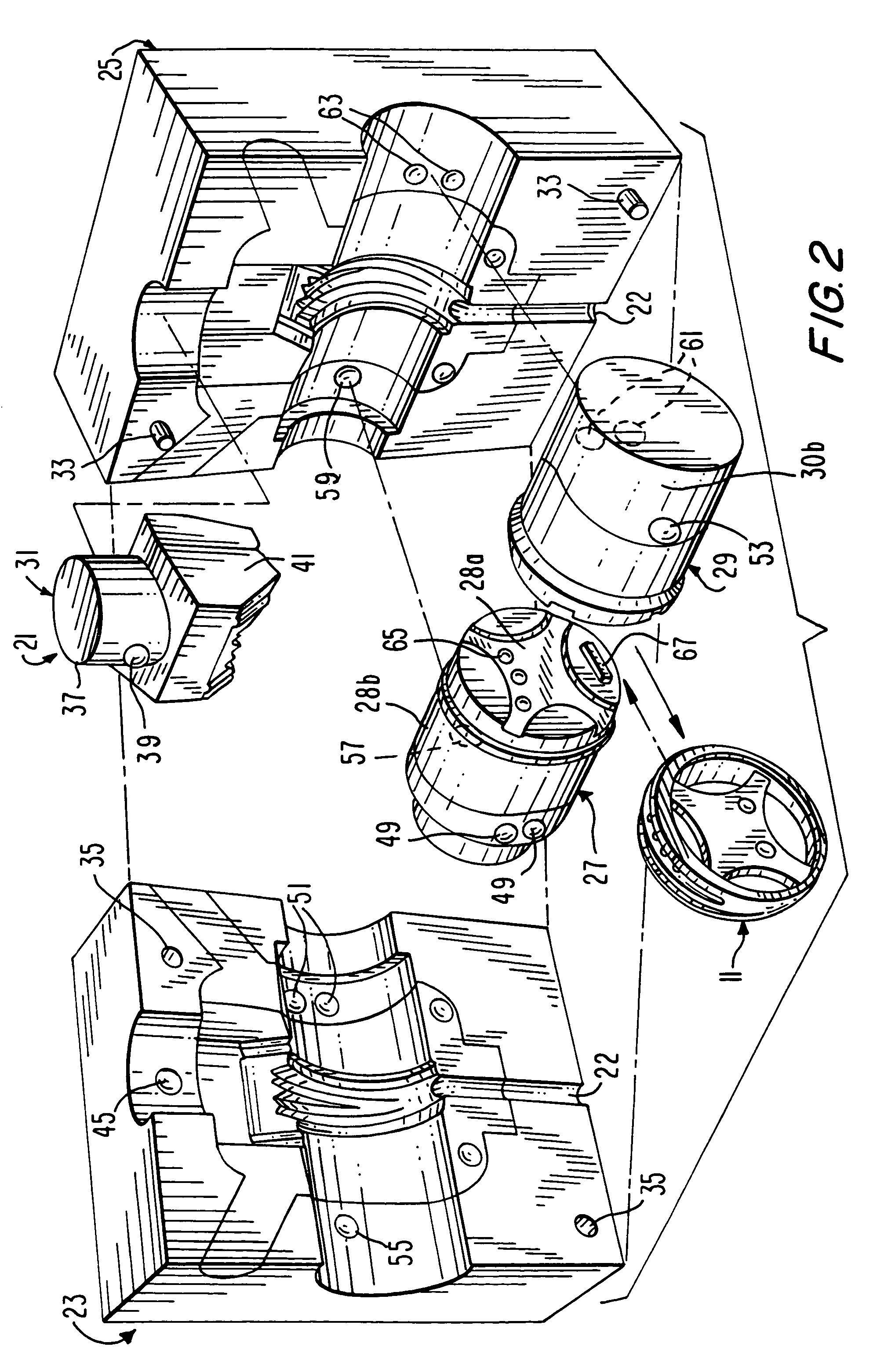
[0039]Referring now to FIG. 2, a metal ring mold produced from metal ring model 11 depicted in FIG. 1 is generally indic...


PUM

PropertyMeasurementUnit
angleaaaaaaaaaa
thicknessaaaaaaaaaa
thicknessaaaaaaaaaa

Abstract

There is provided a method or process for fabricating a hollow jewelry article which is hollowed or bored out. In accordance with this process, a metal ring model is prepared comprising a solid shank and a metal plate supported along the internal perimeter of the shank by means of a series of spokes extending from the shank. A first metal mold is produced from the metal ring model having the external shape of the jewelry article to be manufactured. From this mold, a wax model of the jewelry article is produced which is first filed down and then cast in order to form a metal model of a core insert; the core insert, like the ring model, has a plate disposed along the perimeter of the shank. This core insert is used to produce a second metal mold. This second mold may then be used repeatedly in order to form a soluble wax core insert model which is then inserted into the cavity of the first mold in order to define the hollow region of the article. A non-soluble wax is then introduced into the first mold for completely surrounding the soluble wax core insert. The non-soluble wax then hardens and the entire unit is removed from the first mold, including the soluble wax core. The core is then removed by a suitable water soluble or chemical mechanism. The remaining wax model contains a hollow core running along a substantial portion of the arcuate length of the shank; the shank has a finger facing surface formed with a plurality of openings which lead to said core. The wax model is then cast in order to form the inventive ring design.

Description

BACKGROUND OF THE INVENTION[0001]This invention relates to a method for casting or molding an article of jewelry, and more particularly, to a method for producing a bored out or hollow jewelry article such as a ring.[0002]There are many well known processes used in the large volume production of jewelry. Such processes include die striking, casting and electroforming, all of which are used for producing metallic jewelry articles. Such production methods are capable of facilitating high volume, high speed production with very good reproducibility. For example, using permanent-mold casting or injection molding techniques, a single mold cavity may be used repeatedly to produce, at a low cost, a virtually unlimited number of jewelry articles of intricate detail and varying size.[0003]In order to reduce production costs in the manufacture of jewelry articles, previous improvements have generally focused upon-better equipment; very little effort has been directed to actually modifying the...

Claims


Application Information

Patent Timeline
Patent Type & Authority Patents(United States)
IPC IPC(8): B22C9/02B22C9/00
CPCB22C7/02B22D25/026B22C9/04
Inventor HASHIMAN, ERVANTAYVAZIAN, GARABED
Owner QUALITY CASTING
Why Eureka
Try Eureka