
Electronically controlled aircraft retractable landing light with manual retraction capability

a technology control switches, which is applied in landing aids, lighting and heating apparatus, and electrical switch and relays with limited operational life, etc., can solve the problems of affecting the ability to change the operational characteristics of retractable landing lights, affecting the operation of landing lights, and generating electromagnetic interference. , to achieve the effect of reducing electromagnetic emissions, limiting electrical stress, and reducing electrical nois

Inactive Publication Date: 2006-07-25
HONEYWELL INT INC
View PDF18 Cites 11 Cited by
  • Summary
  • Abstract
  • Description
  • Claims
  • Application Information

AI Technical Summary

Benefits of technology

[0015]This invention is directed to an electronically controlled retractable landing light. The retractable landing light utilizes contactless absolute position sensing to detect the position of the lighthead. The retractable landing light also incorporates electronic control of the brake, motor, and lamp. An improved means of manually retracting the lighthead allows the aircraft to be dispatched in spite of a failure of the retractable landing light.
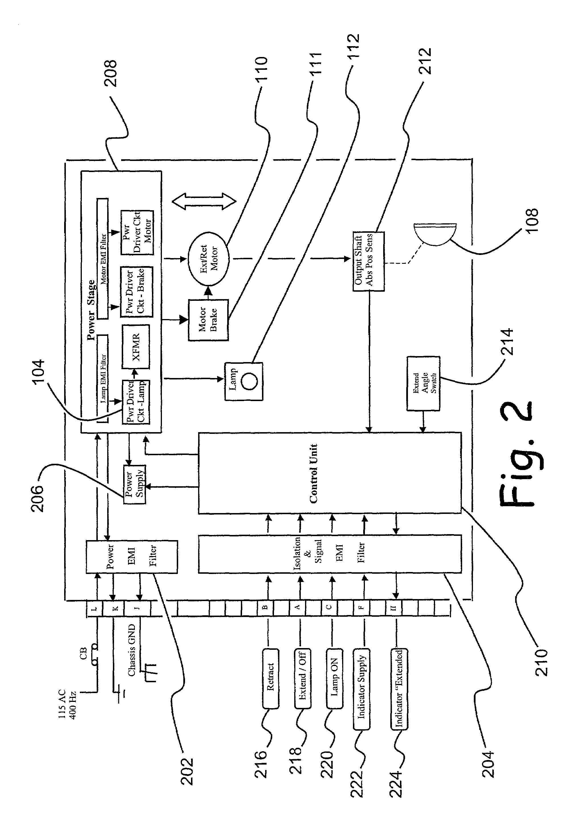
[0016]Specifically, the present invention includes filters to isolate electrical noise between the retractable landing light and the aircraft. A power supply is used to convert the power supplied by the aircraft to a level compatible with the retractable landing light. A power stage utilizes solid state switches with “soft-switching” capability to limit electrical stress on the solid-state switches when turning the brake, motor, and lamp on and off. This soft-switching capability reduces electromagnetic emissions from the brake, motor, and lamp, and extends the service life of these components. A control unit monitors mode and position command signals and lighthead position pre-sets. The control unit actuates the brake, motor, and lamp to move the lighthead to the commanded position, hold the lighthead in place, and turn the lamp on and off, depending on the mode selected. The control unit also provides proper, synchronized timing of the actuation of the brake, motor, and lamp to eliminate overlapping actuation of these devices for reduced electromagnetic emissions and to minimize the generation of switching transients on the aircraft electrical bus.
[0017]The present invention comprises an electronically controlled retractable light, comprising: means for mounting the retractable light; an electrical motor connected with said mounting means, said motor including a brake; means for reducing speed and amplifying torque coupled to said motor, said speed reducing and torque amplifying means being environmentally sealed; a lighthead connected movably with said mounting means and connected with said speed reducing and torque amplifying means, said lighthead including at least one lamp; contactless means for monitoring absolute position of said lighthead; at least one solid state switch, wherein said solid state switch slowly activates and deactivates; and a control unit communicating with said position monitoring means to: monitor the position of said lighthead; provide timed actuation of said brake, motor, and lamp to prevent simultaneous actuation of said brake, motor and lamp; and to stow said lighthead or position said lighthead at a predetermined angle.

Problems solved by technology

Electromechanical switches and relays have limited operational life due to mechanical wear.
In addition, these switches and relays generate electromagnetic interference due to arcing at their electrical contacts.
Electromechanical switches also hinder the ability to change the operational characteristics of the retractable landing light.
Another drawback of electromechanical switches is that they do not lend themselves to precise position control due to the limited resolution of actuators.
Conversely, if the lighthead extension angle is too great, the lamp will be aimed too far ahead of the aircraft.
Both conditions result in a reduction in visibility for the flight crew.
Attempts to implement more precise mechanical position controls in prior retractable landing lights have resulted in more complex actuators, reducing the reliability of the retractable landing light.
Mechanical wearing of the actuators, combined with changes in setting due to vibration, also contributes to shifting of the lamp extension angle over time, requiring regular maintenance to re-adjust the lighthead to the proper angle.
A further disadvantage of electromechanical switches and relays is that current flow through the motor, brake and lamp is limited only by the capacity of the aircraft's electrical system and wiring.
This places significant stress on the relay contacts, motor, brake, and lamp, causing these components to suffer reduced service life.
This involves a time-consuming manual adjustment of position-control limit switches and repeated cycling of the retractable landing light.
Over time, exposure to the elements when the lighthead is extended causes a loss of gearbox lubrication.
Low viscosity grease is used to counter this loss, but at the expense of gearbox efficiency, particularly at low temperature extremes.
Retractable landing lights inherently have a failure mode whereby the lighthead cannot be retracted.
The aircraft cannot be dispatched in this condition, requiring maintenance personnel to remove and replace the retractable landing light.
This can cause significant delays in the dispatch of the aircraft, particularly if the failure occurs at a remote location with limited maintenance capability.
Although prior retractable landing lights have included manual retraction capability, the release mechanisms are slow and cumbersome.
Potentiometers are subject to wear-out, limiting the service life of the aircraft light.
Further, Hamilton does not teach how to preconfigure the operating envelope of an articulating light for different aircraft models, since the preset positions disclosed in Hamilton define only the operating envelope limits for the lighthead.
Also, Hamilton does not disclose how to reduce electromagnetic emissions and extend the service life of the motor brake and motor.
However, the position sensing disclosed in Metz does not accommodate reconfiguration of the operating envelope for different aircraft models, necessitating trial-and-error adjustment.

Method used


Image

  • Electronically controlled aircraft retractable landing light with manual retraction capability
  • Electronically controlled aircraft retractable landing light with manual retraction capability
  • Electronically controlled aircraft retractable landing light with manual retraction capability

Examples


Embodiment Construction

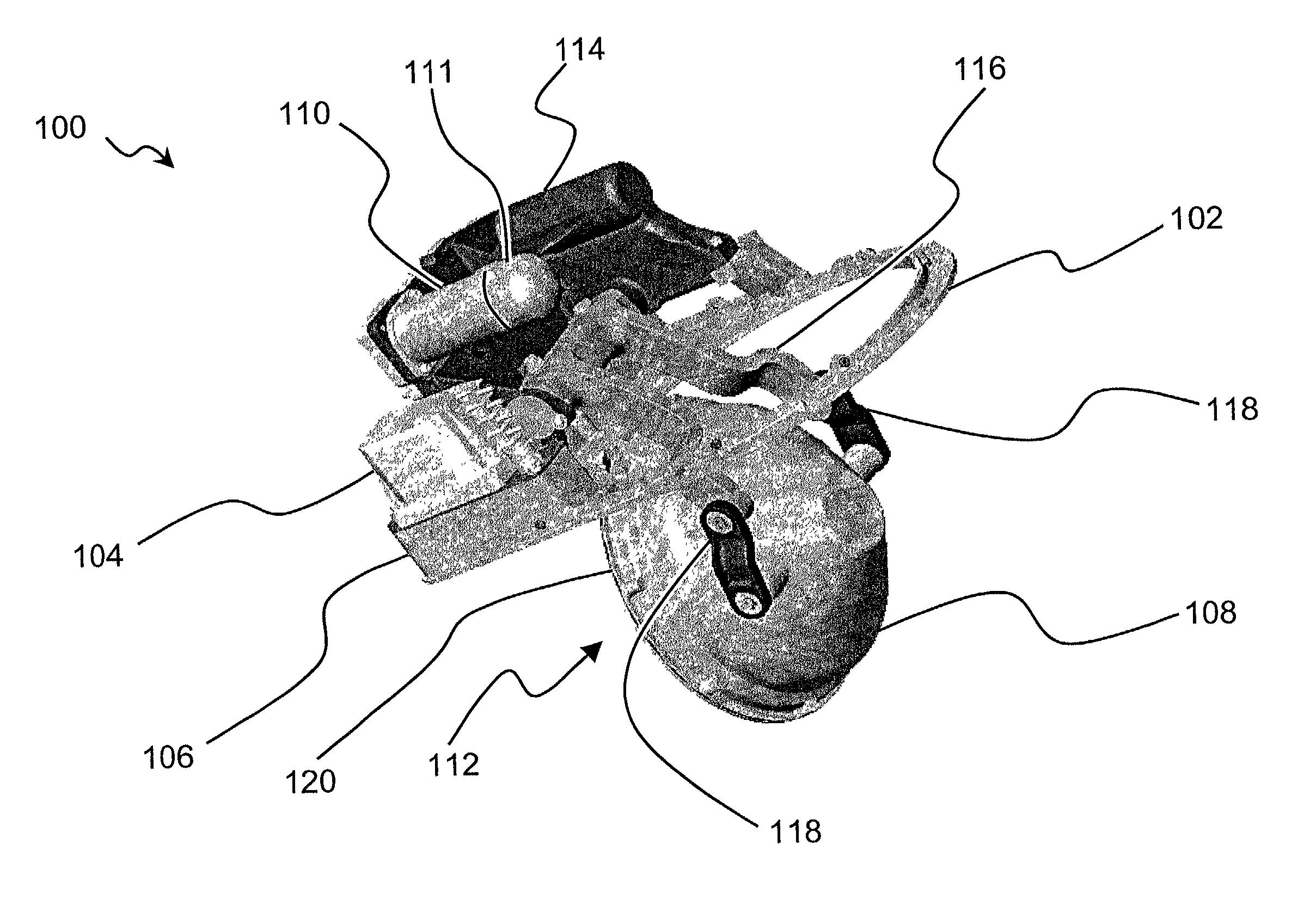
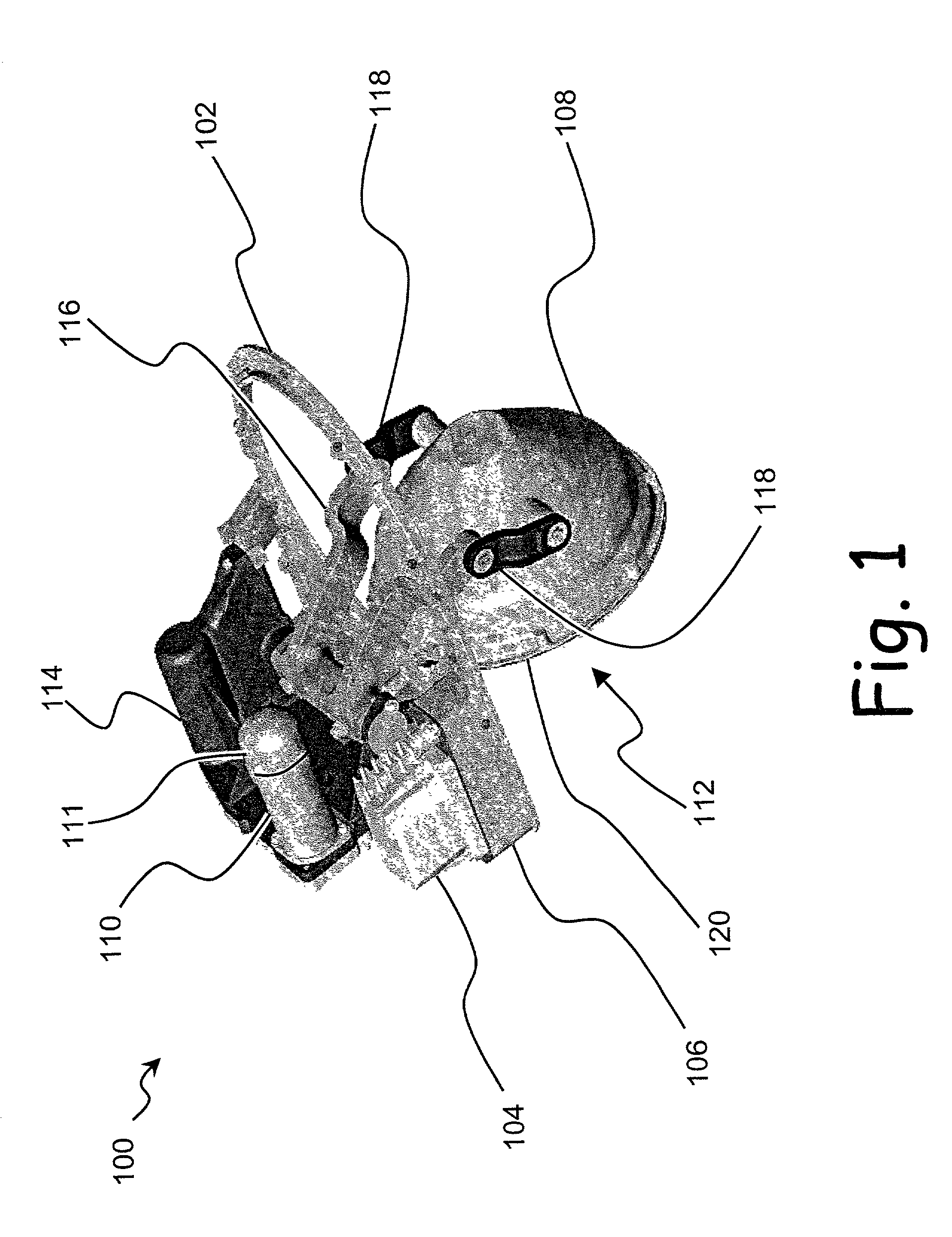
[0022]A retractable landing light 100 is shown in FIG. 1. A baseplate or mounting means 102 is a chassis and also facilitates mounting of the retractable landing light 100 into an aircraft. Power from the aircraft is converted to a level compatible with a lamp 112 by a transformer 104. A controller 106 monitors the position of a lighthead 108. The controller 106 also provides “soft start” solid-state power switching of a motor 110, a brake 111, and the lamp 112 to extend the life of the motor 110, brake 111, and lamp 112 and reduce electromagnetic emissions. In addition, the controller 106 may provide protection from fault conditions such as excessive current or over-temperature conditions, a stalled motor 110, and blockages to the lighthead 108. Further, the controller 106 easily facilitates changes to the setpoint of the lighthead 108 and the addition of new functions. The controller 106 may optionally include means for regularly flashing the lamp 112 on and off or from a higher v...


PUM


Abstract

An electronically controlled retractable landing light (100) for use with aircraft. A controller (106) compares the commanded position of a lighthead (108) by means of a contactless absolute position sensor (212). Operation of a brake (111), motor (110), and lamp (112) is controlled by a control unit (210). Electrical power to the brake (111), motor (110), and lamp (112) is slowly applied and removed to reduce electromagnetic emissions and extend the service life of a power stage (208), brake (111), motor (110), and lamp (112). The lighthead (108) may be manually stowed in the event of a fault.

Description

CROSS REFERENCE[0001]This application is related to a application entitled “Efficient Solid State Switching and Control System for Retractable Landing Lights,” by inventors D. Melvin and S. Mubaslat, filed concurrently with the present application, and issued as U.S. Pat. No. 6,608,445.[0002]This application claims the benefit of U.S. Provisional Application No. 60 / 339,635 filed Dec. 12, 2001 entitled “Electronically Controlled Retractable Landing Light.”BACKGROUND OF THE INVENTION[0003]1. Field of the Invention[0004]This invention relates to aircraft retractable landing lights. Specifically, the invention is directed to an aircraft retractable landing light having electronic position control and switching with manual lighthead retraction capability.[0005]2. Description of the Related Art[0006]Landing lights are mounted to aircraft to illuminate the area forward of the aircraft during night operations on taxiways and runways. A “retractable landing light” is a remotely controlled, a...

Claims


Application Information

Patent Timeline
Patent Type & Authority Patents(United States)
IPC IPC(8): B60Q1/02B60Q1/00B60Q11/00B64D47/04
CPCB64D47/04
Inventor BARNHART, BRIAN J.GIFFEN, CRAIG E.HAMILTON, SCOTT E.MUBASLAT, SAED M.
Owner HONEYWELL INT INC
Learn More