Syringe and prefilled syringe

a syringe and pre-filled technology, applied in the field of syringe and pre-filled syringe, can solve the problems of difficult to push the pusher for discharging liquid, complicated operation at the time of use, and poor operability of discharging liquid chemicals

Inactive Publication Date: 2006-07-25
TERUMO KK
View PDF13 Cites 53 Cited by
  • Summary
  • Abstract
  • Description
  • Claims
  • Application Information

AI Technical Summary

Benefits of technology

[0013]It is an object in a broad sense of the present invention to provide a syringe structure and a prefilled syringe capable of assuring, by themselves, the sanitation of a syringe outer tube when not in use, allowed to be shipped without being individually packaging with a packaging material, and providing excellent operability of discharging (injecting) liquid chemicals at the time of use.
[0014]Particularly, it is a first object of the present invention to provide a syringe and a prefilled syringe making it hard for foreign matter such as dirt and dust to enter into the syringe, assuring the sanitation of a syringe outer tube when not in use during storage, transportation or the like, preferably capable of obviating bacterial pollution, making it easy to push or pull a pusher in use, and making it easy to discharge (inject) liquid chemicals.
[0015]It is a second object of the present invention to provide a syringe and a prefilled syringe of a structure capable of surely maintaining the aseptic property of the inside of an outer tube even if the push and pull operations of a pusher are performed.

Problems solved by technology

Therefore, the gap (second space) between the outer tube inside wall and the pusher on the base end side relative to the gasket is in an open condition and, when the open condition is kept as it is, foreign matter such as dirt and dust may enter into the second space together with the outside air or bacterial pollution may occur during storage, transportation or the like, which is disadvantageous on a sanitary basis.
However, the prefilled syringe of the type in which the outer tube and the inner tube are individually sealed with caps has the disadvantage that the operation at the time of using it is intricate and troublesome, since an operation of removing the caps is needed and it is necessary to attach an inner tube tip end portion to the piston in the outer tube and to attach another pushing rod (pusher) to a base end portion of the inner tube (see FIG. 2 of the above-mentioned publication).
However, the gas-tight sealing on the base end side of the outer tube as above-mentioned makes it difficult to push the pusher for discharging the liquid.
In addition, the syringe is shipped in the state of being packaged as above-mentioned, so that, when the pusher is pushed by some force and the gasket is thereby moved inside the outer tube to the tip end direction during transportation or storage, the following troubles are generated.
1) By being pushed by the gasket moved, a cake (a certain-shaped freeze-dried preparation) of a chemical may be collapsed, thereby spoiling the beautiful appearance of the product.
If the chemical has entered into the gap, at the time of feeding the chemical by use of the syringe, the chemical having entered into the gap may be left undissolved in the liquid sucked into the outer tube, causing an error in the amount of the chemical fed.
3) Where the presealed chemical is a liquid (liquid chemical), when the gasket is going to move to the tip end direction, the pressure of the liquid chemical is increased, with the result that the liquid may leak out by breaking the sealing member at the mouth portion or may leak to the base end side of the gasket via the gap between the outer circumferential surface of the gasket and the inner circumferential surface of the outer tube.

Method used


Image

  • Syringe and prefilled syringe
  • Syringe and prefilled syringe
  • Syringe and prefilled syringe

Examples


first embodiment

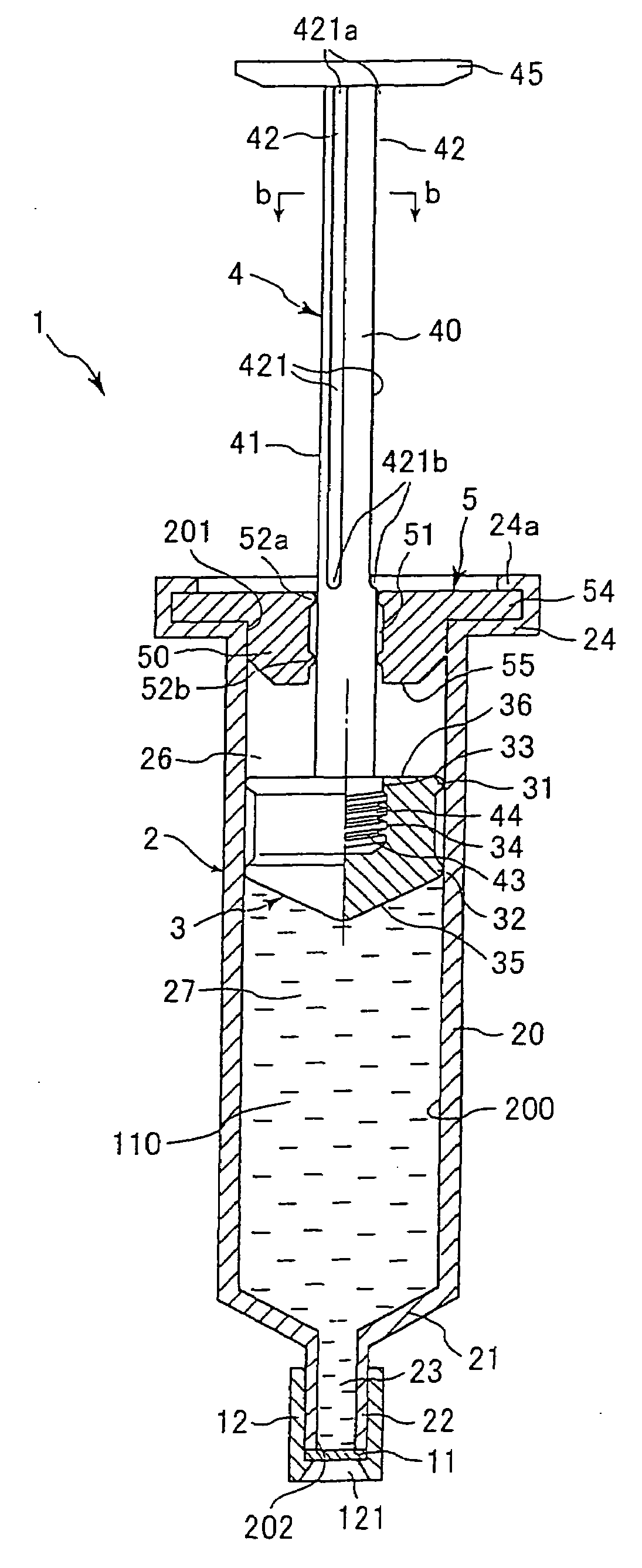
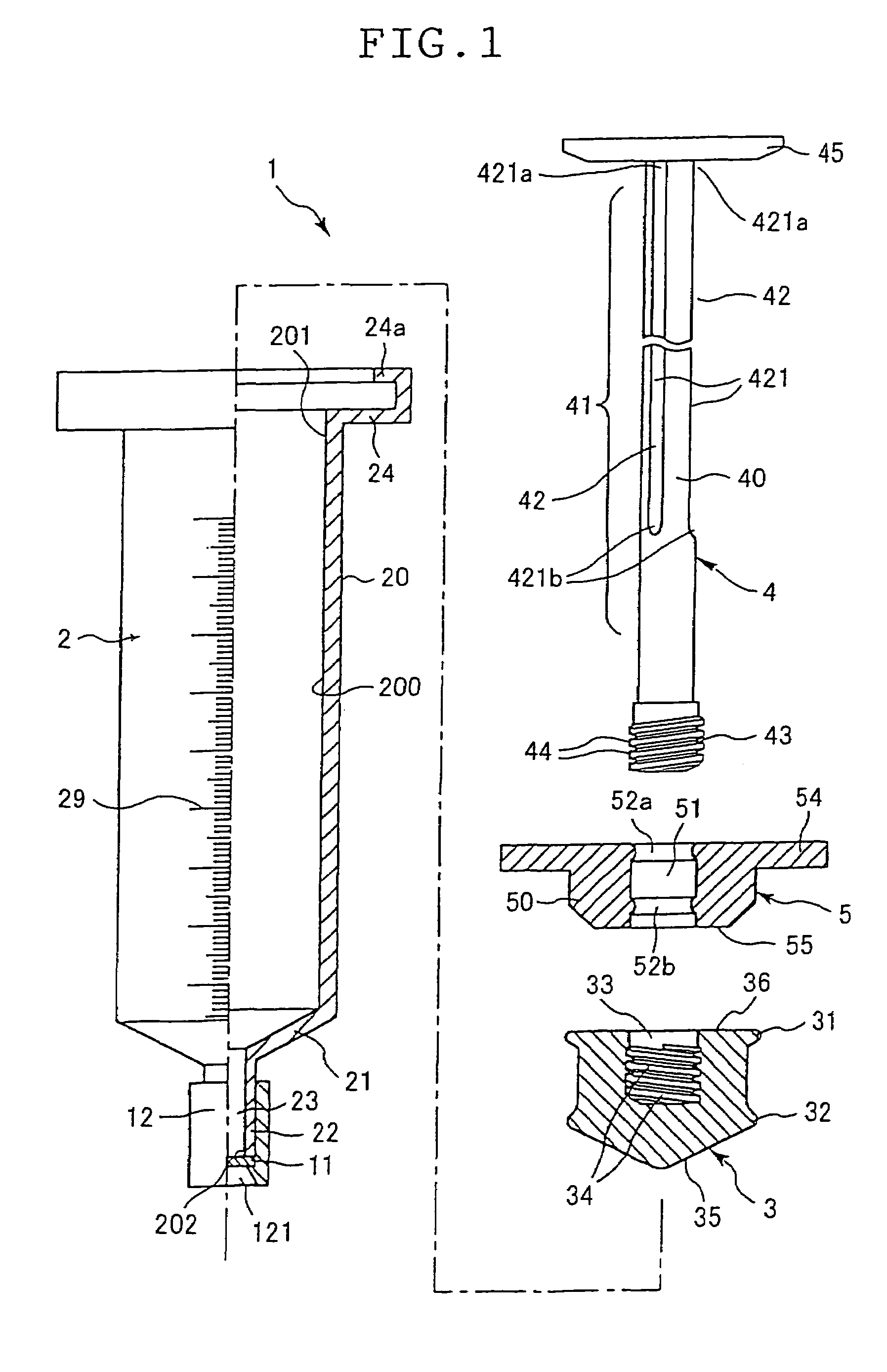
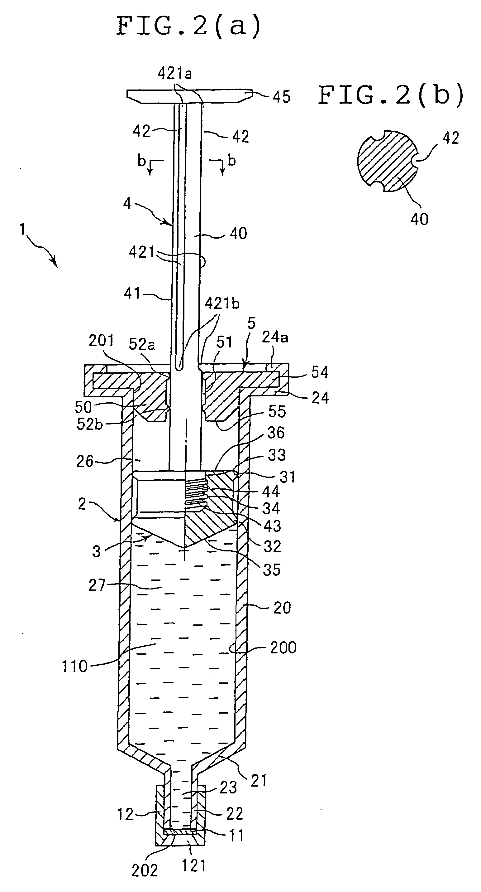
[0087]Now, the first-named invention as above will be more specifically described below, referring to some preferred embodiments. FIGS. 1 to 5 show a prefilled syringe (hereinafter sometimes referred to simply as “syringe”) according to the first-named invention. FIG. 1 is a partial vertical sectional view showing the disassembled state of the syringe before filling with a chemical, for illustrating syringe component members, FIG. 2(a) is a partial vertical sectional view of the assembled state (prefilled syringe) after filling with the chemical, and (b) is a cross sectional view of the pusher. FIGS. 3 to 5 are partial vertical sectional views showing operations in use of the prefilled syringe shown in FIG. 2. Incidentally, in FIGS. 1 to 5 and in FIGS. 6 to 8, which will be described later, the upper side in the figures will be referred to as the “base end” side, while the lower side will be referred to as the “tip end” side.

[0088]The syringe 1 in this embodiment comprises an outer ...

third embodiment

[0157]In the syringe 1 not only in the pre-operation condition but also during injection of the liquid chemical 110 (during introduction of the outside air into the second space 26) and after completion of the injection of the liquid chemical 110, penetration of foreign matter into the second space 26 and penetration of bacteria into the second space 26 can be securely inhibited by selecting the function of the filter 9.

[0158]Therefore, the aseptic property of a first space 27 and the second space 26 can be maintained even in the case where, for example, the pusher 4 and the gasket 3 are reciprocated (for example, where each of the suction of a liquid into the first space 27 and the discharge of the liquid from the first space 27 is conducted at least once).

[0159]Incidentally, the position where the filter 9 is disposed is not limited to the position shown in FIG. 7 but may be at an intermediate portion of the lumen 423 or in the vicinity of the side hole 424. Besides, such a filte...


PUM


Abstract

A syringe (and a prefilled syringe) of a structure with ventilation means allowing a pusher to be easily pushed or pulled in use, providing an excellent operability of discharging (injecting) chemicals, making it hard for foreign matter such as dirt and dust to enter into a syringe outer tube when not in use during storage or transporation, capable of assuring, by itself, the sanitation of the syringe outer tube when not in use, and allowed to be shipped without individually packaging the syringe with packaging material, wherein, as more desirable embodiments, the aseptic condition in the outer tube can be surely maintained even if the push and pull operations of the pusher are performed and, even if the pusher is pushed when not in use, a gasket does not move in tip direction and the arrangement of the pusher at the time of shipping can be stably maintained.

Description

TECHNICAL FIELD[0001]The present invention relates to a syringe and a prefilled syringe in which a chemical is preliminarily contained.BACKGROUND ART[0002]A syringe is generally composed of an outer tube provided on the tip end side thereof with a mouth portion reduced in diameter, a gasket inserted in the outer tube via a base end opening of the outer tube, and a pusher (plunger rod) connected to the gasket.[0003]A prefilled syringe with a chemical preliminarily contained (sealed) in a syringe is known. The chemical usually is aseptically sealed in a space (first space) on the tip end side relative to the gasket maintained in a hermetically closed condition by a seal at the mouth portion. In using the prefilled syringe containing a liquid chemical as a chemical, for example, the outer tube is usually held by one hand, and the pusher is pushed by the other hand to slide the gasket in the outer tube to the tip end direction, thereby discharging (injecting) the liquid chemical via the...

Claims


Application Information

Patent Timeline
Patent Type & Authority Patents(United States)
IPC IPC(8): A61M5/315A61M5/31
CPCA61M5/315A61M5/31511A61M5/3145A61M2005/3123A61M5/31515A61M2005/3121
Inventor KITO, HIDEAKITACHIKAWA, KOUICHIKASAI, MASAAKI
Owner TERUMO KK
Why Eureka
Try Eureka