Flexible barb for anchoring a prosthesis

a flexible, prosthesis technology, applied in the field of medical devices, can solve the problems of increasing the risk of death of patients, no longer excluding aneuryms, and migration, so as to reduce the risk of fracture, facilitate lateral flexing of the barb, and reduce the likelihood of fractur

Inactive Publication Date: 2006-07-25
COOK MEDICAL TECH LLC
View PDF16 Cites 199 Cited by
  • Summary
  • Abstract
  • Description
  • Claims
  • Application Information

AI Technical Summary

Benefits of technology

[0009]In the illustrative embodiment, the last or distal winding of the helical coil comprises the stress-dispersing region and is typically of a greater pitch than the windings of the basal portion. It also does not include solder or some other bonding means that affixes it to the strut of the prosthesis, nor does it generally contact the strut. This allows the last winding to remain flexible and thus, accommodate the forces acting upon the anchoring portion of the barb, which is embedded in the adjacent tissue. The majority of the stress load acting on the barb is distributed over the entirety of the large-radius helical bend of the winding to reduce the likelihood of fracture, rather than allowing these forces to concentrate about a single point, typically where the barb first extends from the point of union between the barb and the strut (and solder joint in this particular embodiment). In a related embodiment, the second end of the barb can comprise a second anchoring portion and stress-dispersing region extending oppositely from the basal portion and area of fixation to form a double-ended barb.
[0010]In another aspect of the invention, the basal portion of the strut is secured to the strut with a piece of cannula or similar structure that is crimped or bonded in place, such as with the illustrative solder joint. The stress-dispersing region comprises a pair of bends that facilitate lateral flexing of the barb to reduce the risk of fracture. In a related embodiment, the barb extends from the solder joint, then assumes a series of stress-dispersing bends that are proximal to the anchoring portion.
[0011]In yet another aspect of the present invention, the stress-dispersing region of the barb comprises a coiled loop bend, U-shaped bend, or other series of bends distal to the point of attachment to add flexibility to the barb, thus reducing bending fatigue and the risk of barb fracture. The barb may include both a coiled loop bend (or other type of bend) and a free helical winding to add further flexibility.

Problems solved by technology

Migration can be a significant problem in the placement of expandable stents and other intraluminal devices, particularly when placed in the vascular system where the prosthesis is subject to the forces of blood flow, especially on the arterial side.
Nowhere is the prevention of migration more important and more challenging than when placing a stent graft to repair an abdominal aortic aneursym (AAA) where downstream migration of the device can result in the aneursym no longer being excluded.
If the aneurysm is no longer intact or subsequent rupture were to occur, the patient would then face an increased risk of death.
It has been observed that sutures attaching barbed stents to the graft material are subject to breakage due in part to the flexibility of the graft material and the considerable pulsatile forces of arterial blood acting on the device.
It has also been observed that barbs soldered or otherwise attached to the stent frame are subject to fracture, detachment, or other failure, especially when the forces become concentrated at a particular location along the stent graft.
Unfortunately, simply making the barbs stronger to prevent fracture can result in increased damage to the anchoring tissue.
Furthermore, adding rigidity to any outward-projecting barbs may compromise the ability of the device to be compressed and loaded into a delivery system.

Method used


Image

  • Flexible barb for anchoring a prosthesis
  • Flexible barb for anchoring a prosthesis
  • Flexible barb for anchoring a prosthesis

Examples


Embodiment Construction

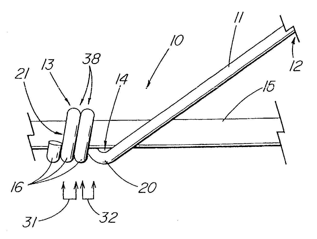
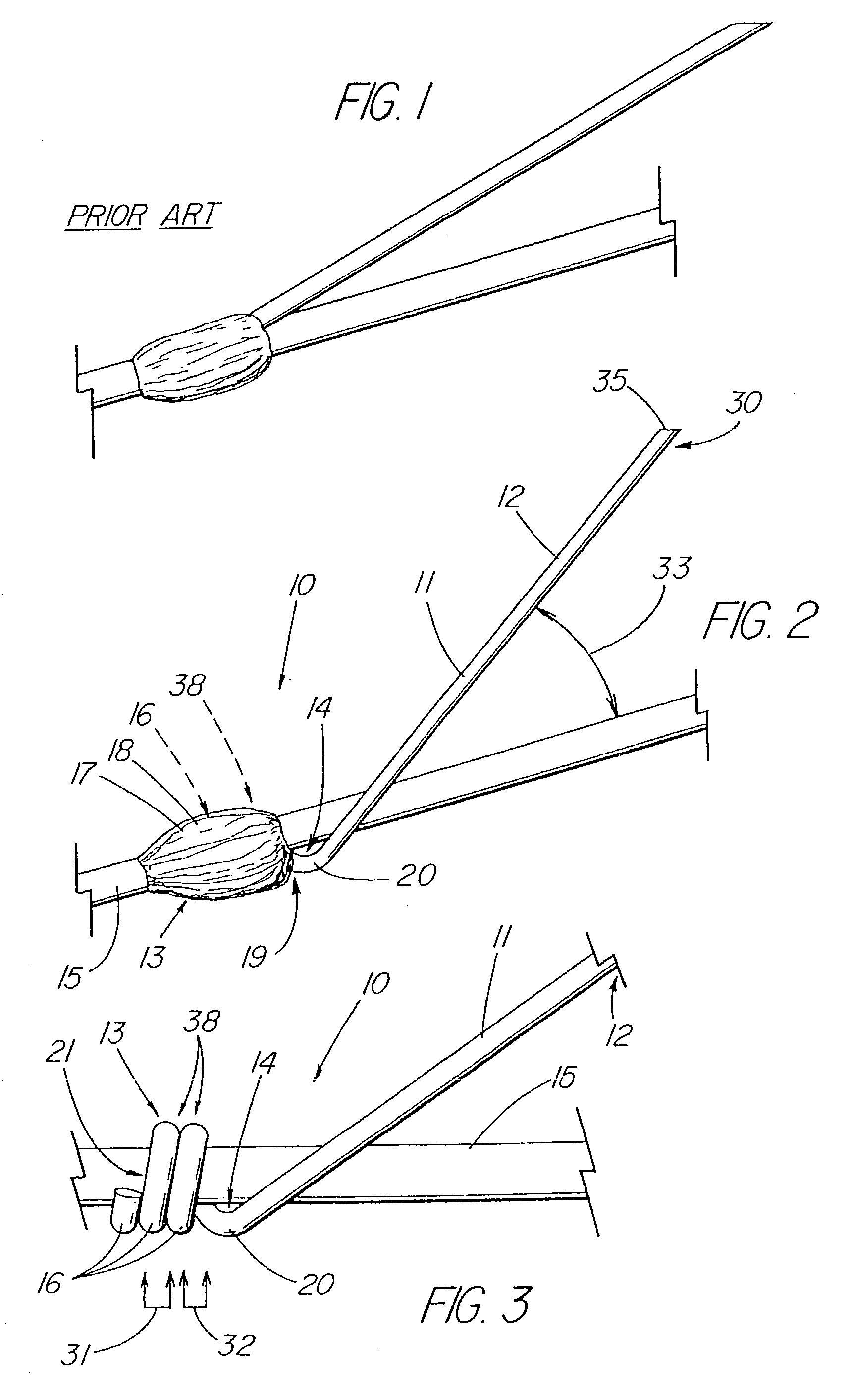
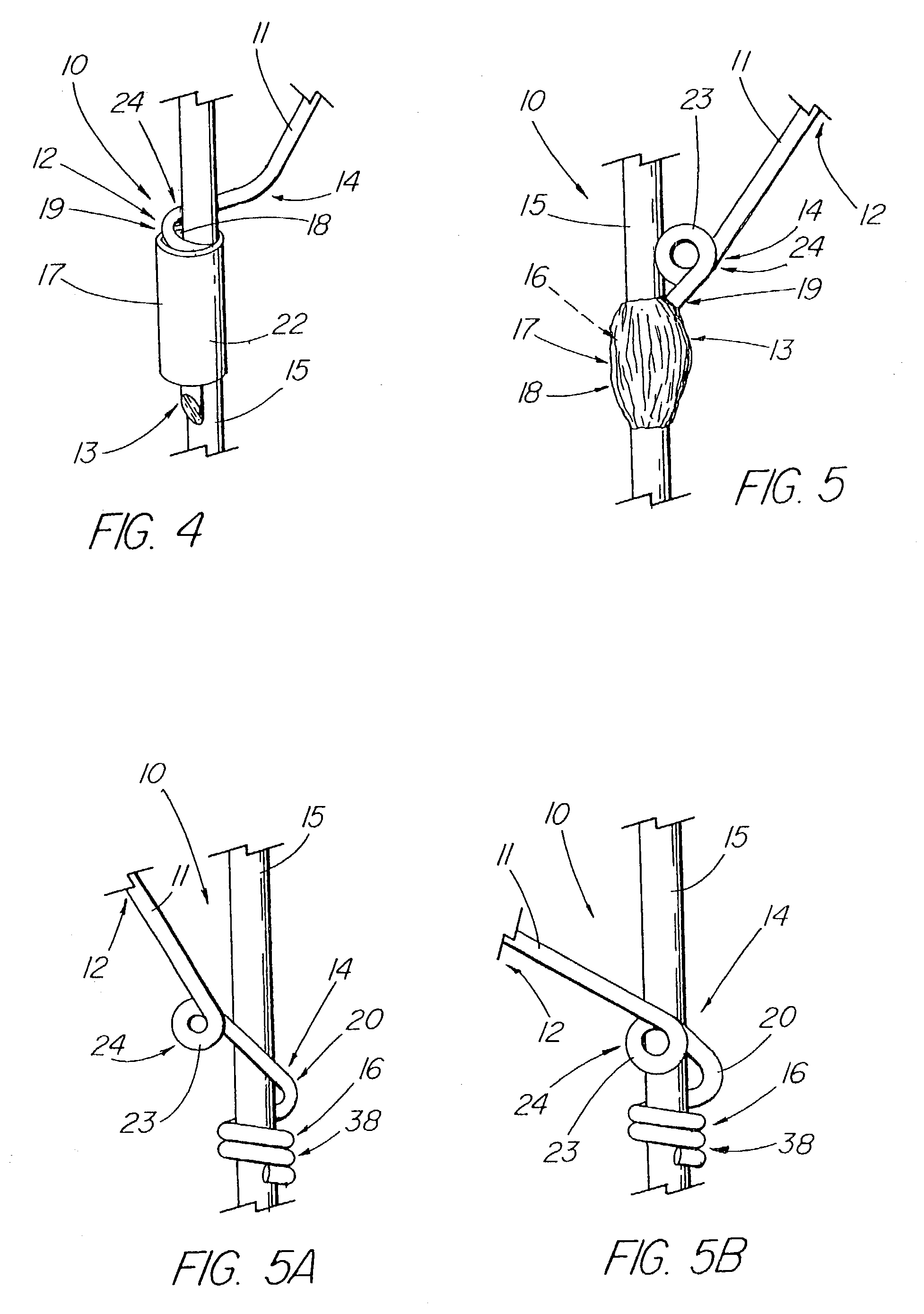
[0022]FIGS. 2–8 depict a medical prosthesis 10, such as a stent, stent graft, valve, vessel occluder, filter, or other intraluminal medical device, that includes one or more barbs 11 that comprise an anchoring portion 12 sized and oriented to engage tissue for the purpose of anchoring the device and preventing the downstream migration thereof; a basal portion 13 located about the physical union between the barb and the strut of the prosthesis 10 to which it is affixed; and a stress-dispersing region that forms a transition between the basal portion 13 and anchoring portion 12 of the barb 11. The stress-dispersing (or stress-reducing) region 14 of the present invention comprises a section of the barb that has been shaped and configured to receive most of the forces acting upon the anchoring portion 12 or moment arm of the barb as it bends and distribute them throughout that region 14, rather than allowing them to be concentrated at a single point or relatively narrow region, such as ...


PUM


Abstract

A barbed medical prosthesis is disclosed in which the barb includes a basal portion comprising a point of union with the substrate of origin (such as a strut), an anchoring portion adapted to embed into tissue, and a stress-dispersing portion located between the basal and anchoring portions. In one embodiment the stress-dispersing portion comprises a helical coil having a free winding that is unattached to the strut from which the barb extends. In another embodiment, the stress-dispersing portion comprises a series of bends or curves formed in the barb proximate to the point of union with the strut. The barb can be mechanically attached and / or soldered to the prosthesis, or integrally formed therefrom. A second barb portion and stress-dispersing portion, may also extend from the basal portion.

Description

CROSS-REFERENCE TO RELATED APPLICATIONS[0001]This application claims priority of provisional application Ser. No. 60 / 381,046, filed May 16, 2002.TECHNICAL FIELD[0002]This invention relates to medical devices, more particularly to stents and other prosthetic devices having anchoring barbs.BACKGROUND OF THE INVENTION[0003]Migration can be a significant problem in the placement of expandable stents and other intraluminal devices, particularly when placed in the vascular system where the prosthesis is subject to the forces of blood flow, especially on the arterial side. Nowhere is the prevention of migration more important and more challenging than when placing a stent graft to repair an abdominal aortic aneursym (AAA) where downstream migration of the device can result in the aneursym no longer being excluded. If the aneurysm is no longer intact or subsequent rupture were to occur, the patient would then face an increased risk of death. Unlike surgically placed grafts which are sutured...

Claims


Application Information

Patent Timeline
Patent Type & Authority Patents(United States)
IPC IPC(8): A61F2/06A61F2/82
CPCA61F2/82A61F2002/8483A61F2/848
Inventor COOK, WILLIAM A.DEBRUYNE, MICHAEL P.NICKLESS, BENJAMINOSBORNE, THOMAS A.
Owner COOK MEDICAL TECH LLC
Why Eureka
Try Eureka