Orthogonal pulse range ambiguity resolution

a range ambiguity and orthogonal pulse technology, applied in the field of active range determination systems, can solve the problems of longer time required to produce all the information, pulse duration, transmitted energy,

Active Publication Date: 2006-07-25
LOCKHEED MARTIN CORP
View PDF11 Cites 35 Cited by
  • Summary
  • Abstract
  • Description
  • Claims
  • Application Information

AI Technical Summary

Problems solved by technology

The tradeoff is that a longer time is required to produce all the information required for an uneclipsed view of the region.
The reduction of the pulse duration, however, tends to reduce the transmitted energy, which reduces the range sensitivity, which again requires a longer period of integration in order to obtain the same effective range.
The reduction of the duty cycle and increase in the pulse repetition interval, however, tends to consume additional radar resources resulting in a greater overall time required for completion of a surveillance scan.
The additional dwells or transmissions consume additional radar resources, resulting in a greater overall time required for completion of a surveillance scan.
The signals received from such a remote target tend to be weak, and may be obscured by reflections from a closer target or clutter.

Method used


Image

  • Orthogonal pulse range ambiguity resolution
  • Orthogonal pulse range ambiguity resolution
  • Orthogonal pulse range ambiguity resolution

Examples


Embodiment Construction

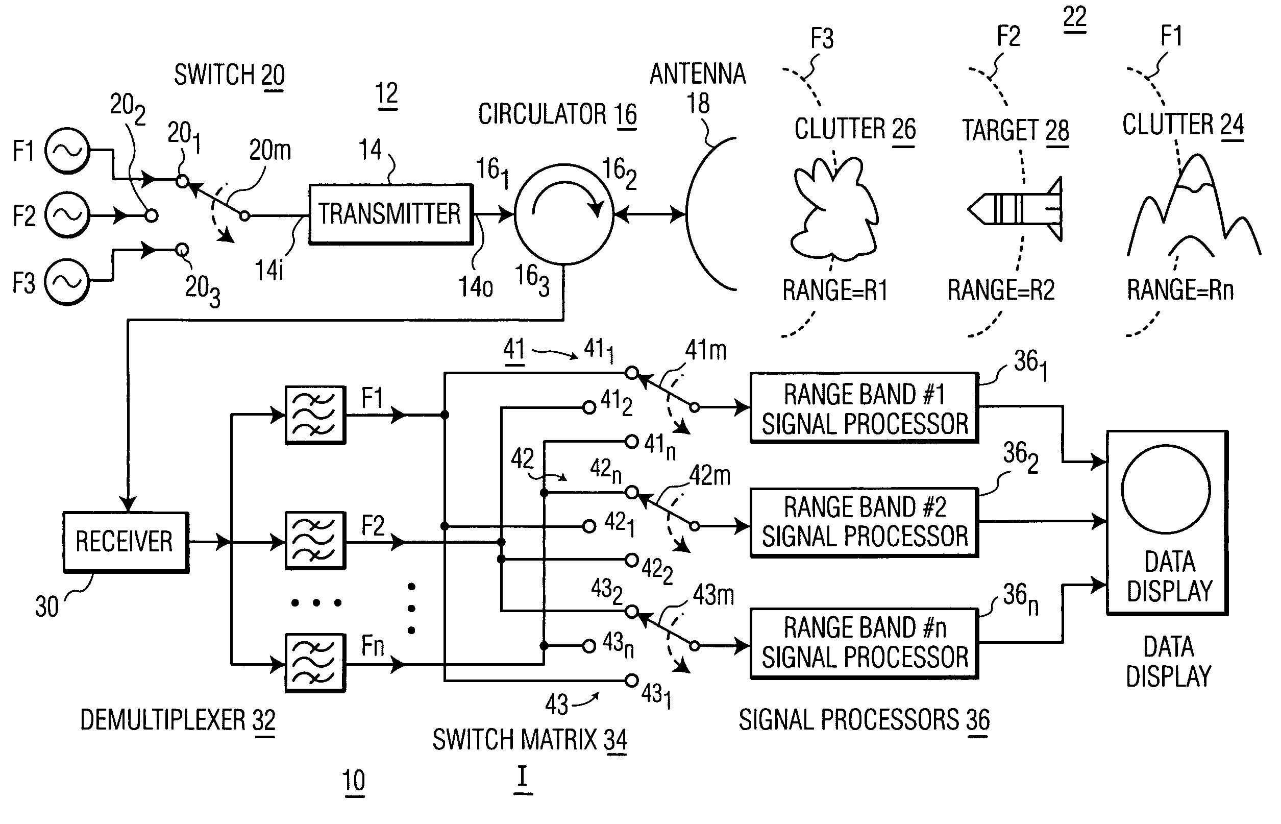
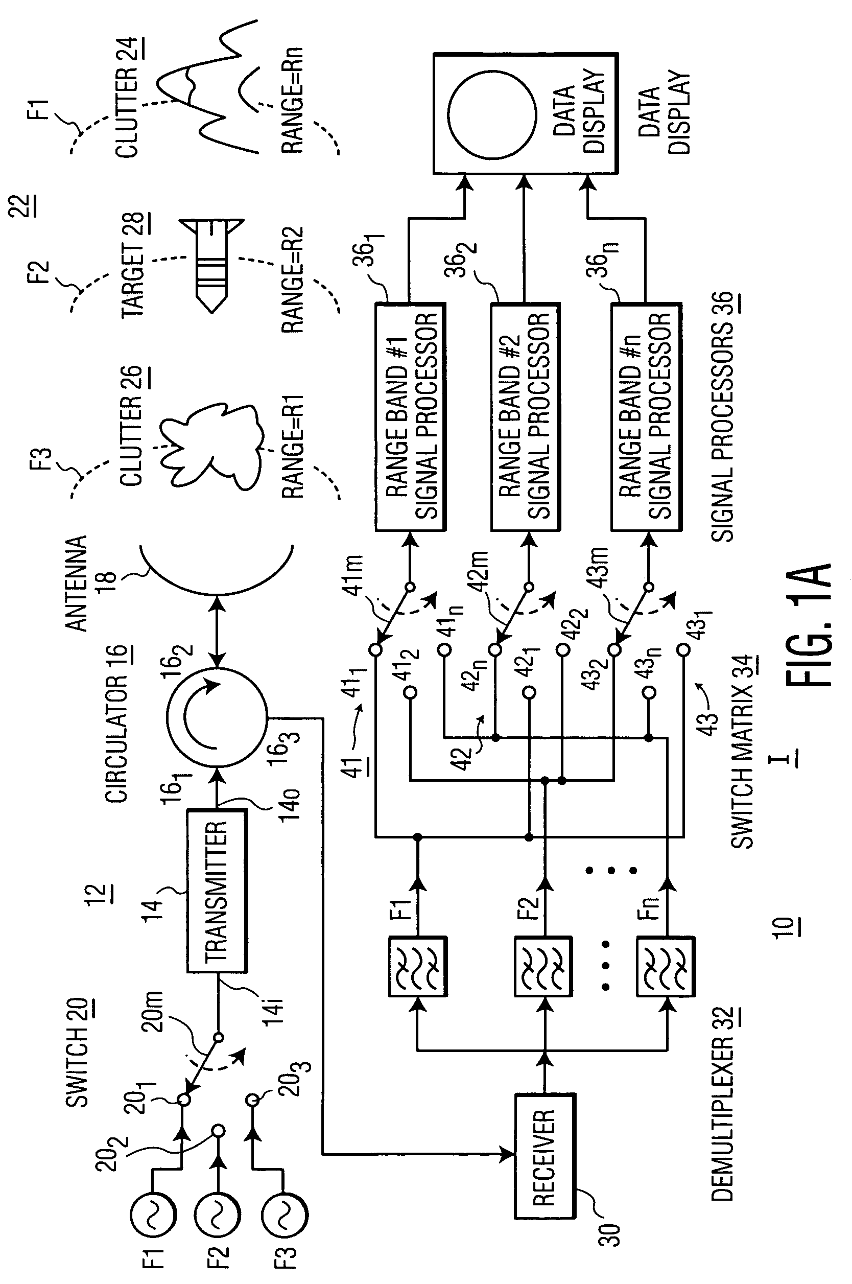
[0021]In FIG. 1a, a radar system 10, which is taken to be representative of any type of active ranging system such as sonar or lidar, includes a transmitter arrangement designated generally as 12. Transmitter arrangement 12 includes a transmitter illustrated as a block 14, the output port 14o of which is coupled by way of ports 161 and 162 of a circulator 16 to an antenna represented as a reflector 18. Those skilled in the art know that other types of antennas, such as arrays, can be used. First, second and third waveform generators WF1, WF2, and WF3 are coupled to terminals 201, 202, and 203, respectively, of a switch 20. Switch 20 is conventionally represented as being a mechanical single-pole, triple-throw switch, but those skilled in the art will understand that this is but a convention for ease of understanding, and that electronic switch equivalents are used in practice. A movable member 20m of switch 20 sequentially contacts terminals 201, 202, and 203 during operation, there...


PUM


Abstract

A method for active ranging, such as radar, which sequentially transmits pulses of mutually different waveforms. Receive processing is performed concurrently for all the transmitted waveforms during each interpulse interval, to thereby provide range ambiguity resolution together with continuous return signal integration.

Description

FIELD OF THE INVENTION[0001]This invention relates to active range determination systems such as radar, sonar and the like, and more particularly to reduction of range ambiguity.BACKGROUND OF THE INVENTION[0002]Radar and other active range determination systems are in widespread use for military, commercial, and private purposes. Radar systems have well-known characteristics, in that long-range detection of small targets is known to require transmission of more power, higher-gain antennas, and or more sensitive receivers than that or those required for short-range detection of large targets. Among the characteristics of radar systems used for detecting targets at long range are those relating to range ambiguity, which has to do with reception of signals returned from a target lying beyond the range defined by the pulse repetition interval, which may make the distant target appear to be near the radar system. Another such characteristic of radar is that of range eclipsing, which has ...

Claims


Application Information

Patent Timeline
Patent Type & Authority Patents(United States)
IPC IPC(8): G01S13/08
CPCG01S13/24G01S7/2923
Inventor ADAMS, GREGORY F.
Owner LOCKHEED MARTIN CORP
Why Eureka
Try Eureka