Method and apparatus for providing polarization insensitive signal processing for interferometric sensors

a technology of interferometer and signal processing, applied in the field of interferometer, can solve the problems of fiber inducing phase noise, imbalance equal to the difference in time-delay experienced, and unbalanced interferometer

Active Publication Date: 2006-07-25
OPTOPLAN
View PDF11 Cites 26 Cited by
  • Summary
  • Abstract
  • Description
  • Claims
  • Application Information

AI Technical Summary

Benefits of technology

[0014]In a first embodiment of the invention, a pulsed source for the interferometric sensor array is used. The SOP of the interrogation pulses is controlled individually so that two interfering pulses may originate from interrogation pulses that have different SOP such that at least four components of the detected signal can be separated and processed to extract a phase measurement from the response Jones matrix without error caused by polarization induced fading or noise caused by birefringence fluctuations in the lead fibers.

Problems solved by technology

If the nominal path lengths are different, the interferometer is said to be unbalanced, and the imbalance is equal to the difference in time-delay experienced by the light propagating in the two paths.
Thus, if the sensor is birefringent, fluctuations in the SOP of the lead fiber will induce phase noise.
The noise performance of such sensor arrays may be limited by the polarization fluctuations in the lead fiber induced by environmental effects.
The polarization-induced phase noise can be eliminated using depolarized light; however this method does not solve the fading problem.
Furthermore, the Faraday rotating mirrors may be expensive, space consuming, and sensitive to extreme thermal, electromagnetic and other environmental conditions.
When several sensors are multiplexed, this method requires input-polarization control of each multiplexed sensor, which makes it impractical for remote and inaccessible sensor arrays.
These techniques require relatively complex systems to provide feedback signals to the polarization controller.
Thus, the minimum detection bandwidth required for this method is much larger than necessary for CW interrogation of interferometric sensors.
This high detection bandwidth makes this method impractical for TDM two-pulse interrogation.

Method used


Image

  • Method and apparatus for providing polarization insensitive signal processing for interferometric sensors
  • Method and apparatus for providing polarization insensitive signal processing for interferometric sensors
  • Method and apparatus for providing polarization insensitive signal processing for interferometric sensors

Examples


first embodiment

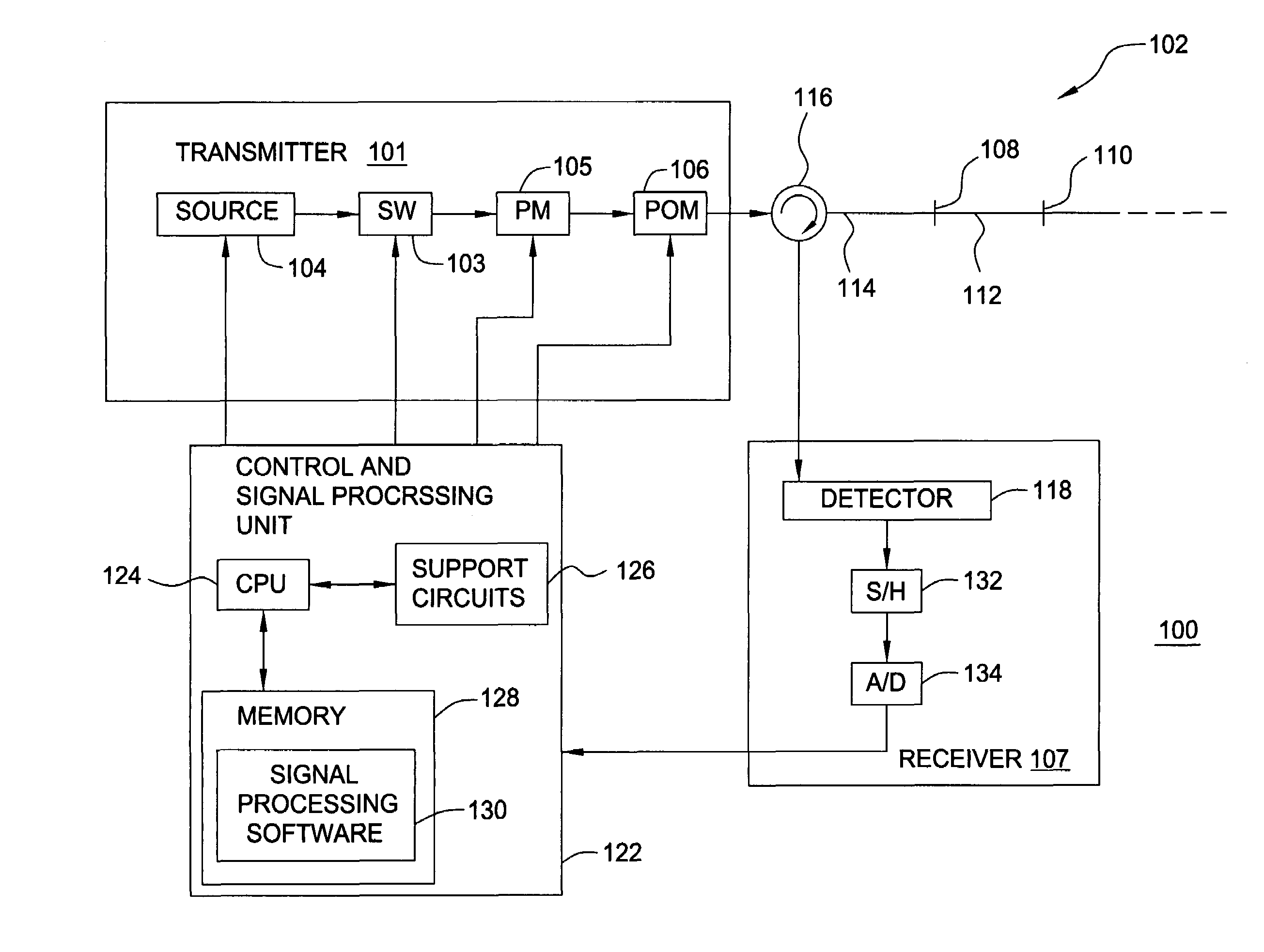
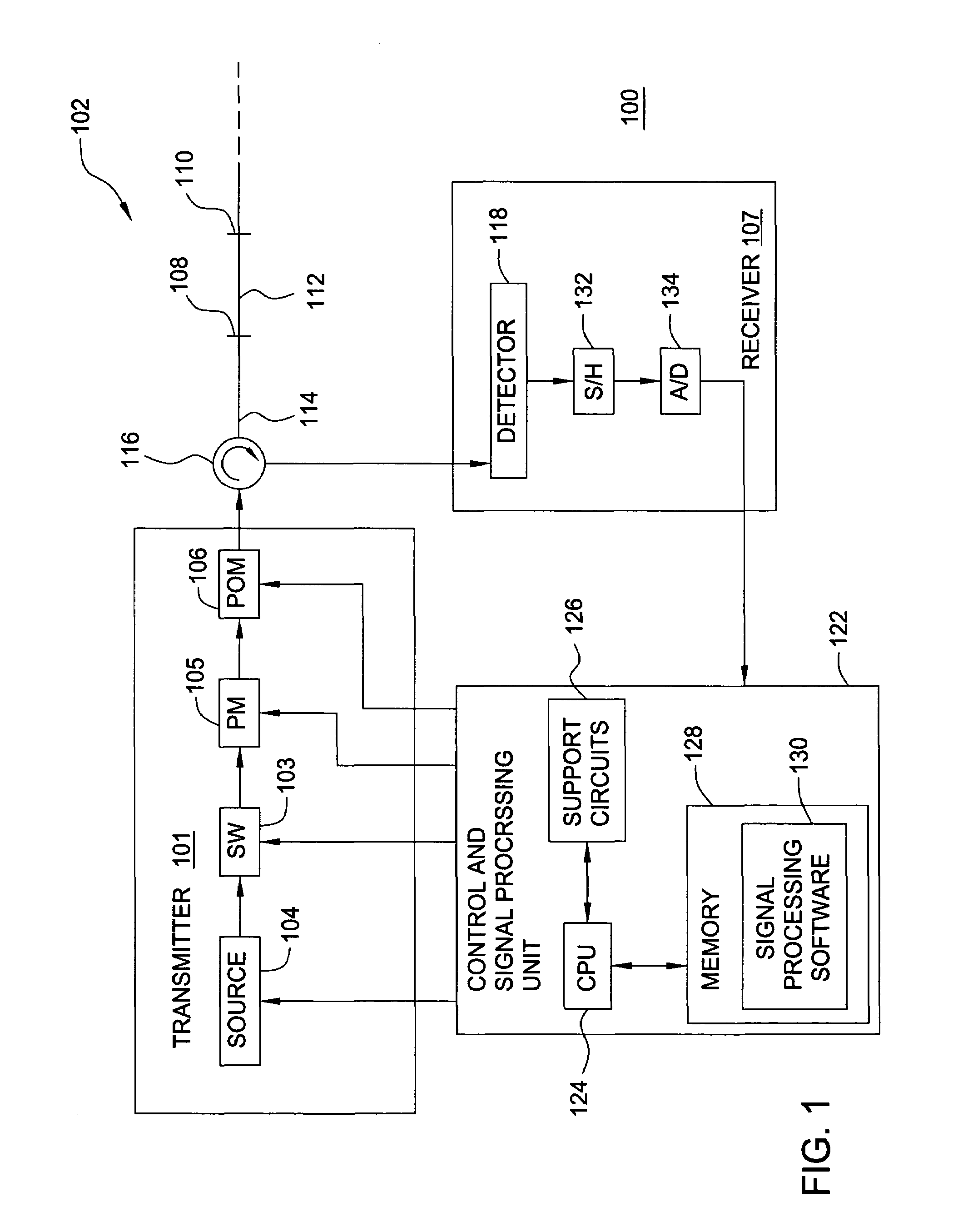
[0030]FIG. 1 depicts the present invention incorporated into an optical interferometer sensor system 100. The optical interferometer sensor system 100 comprises a transmitter 101, a receiver 107, an optical circulator 116, a sensor array 102, and a control and signal processing unit 122. The transmitter 101 comprises a source 104, a Mach-Zender switch 103, a phase modulator 105 and a polarization modulator 106. The receiver 107 comprises a detector 118, a sample-and-hold (S / H) circuit 132 and an analog-to-digital (A / D) converter 134. The source 104 is a light source such as a laser. The light from the source 104 is pulsed by switch 103, phase modulated by phase modulator 105 and polarization modulated by the modulator 106 to form polarization-induced phase noise insensitive interrogation pulses as described below. Preferably, the fibers that interconnect components within the transmitter should be polarization maintaining fibers so that the polarization into the polarization modulat...

second embodiment

[0067]In an alternative version of the second embodiment, the two polarization modulators 304 in FIG. 3 can be used to set the source polarization states in four subsequent measurements to four linearly independent Stokes vectors Sk=└S0k,S1kS2k,S3k┘, k=1, . . . ,4. As an example, if TDM is used, four subsequent interrogation pulse pairs can have horizontal, vertical, 45° linear and right circular polarization states. These states represent four linearly independent Stokes vectors, and matrix R can be found using Equation (14). Although, this choice of transmitter output SOPs might be the preferred embodiment, any four polarization states that can be represented by four linear independent polarization states can be used. This method can also be applied to systems that do not employ TDM, such as WDM or FDM systems or other systems that employ a continuous wave source. In this case the source polarization should be switched between the four polarization states at a rate that is at leas...

third embodiment

[0076]In second version of the third embodiment three-way optical splitter 406 is replaced by a four-way optical splitter, and polarizers with output to only one detector each is used. The power in one of the outputs of the splitter is measured without a polarizer before the detector. This projection is represented by Stokes vector [1,0,0,0]. The three other outputs may project the incoming light to splitter into horizontal(H) SOP, linear 45 degrees (P) SOP and right circular(R)SOP. However, using a polarization diversity receiver not comprising polarization splitters, half the power will be wasted on average compared to a polarization diversity receiver based on polarization splitters. Although these projections of the incoming light may be the preferred embodiments, any other projections can be used provided that four known and linearly independent Stokes vectors can represent the projections.

[0077]In a third version of the third embodiment, a time-varying Stokes analyzer is used....


PUM


Abstract

A method and apparatus that uses specific source modulation and detectors to detect a response that carries information about a system response matrix associated with each sensor in a interferometric sensor array and extracting a sensor response in a manner that eliminates polarization-induced signal fading and that is insensitive to lead fiber birefringence fluctuations.

Description

CROSS-REFERENCE TO RELATED APPLICATIONS[0001]This application contains subject matter that is related to the subject matter described in U.S. patent application Ser. No. 10 / 649,588, filed Aug. 27, 2003 and U.S. patent application Ser. No. 10 / 649,590, filed Aug. 27, 2003, which are both incorporated herein by reference in their entirety.BACKGROUND OF THE INVENTION[0002]1. Field of the Invention[0003]The present invention relates to interferometric sensors and, more particularly, the present invention relates to a method and apparatus for providing polarization-induced phase noise insensitive signal processing for interferometric sensors.[0004]2. Description of the Related Art[0005]When using interferometric sensors, the input light to the sensor is split into two paths (i.e., a reference path and a sensor path) and recombined. The reference path is a path from the transmitter to the receiver via a first path of the sensor, while the sensor path is the path from the transmitter to the...

Claims


Application Information

Patent Timeline
Patent Type & Authority Patents(United States)
IPC IPC(8): G01B9/02G01D5/34G01D5/353
CPCG01D5/345G01D5/35383G01D5/35303
Inventor WAAGAARD, OLE HENRIKRONNEKLEIV, ERLEND
Owner OPTOPLAN
Why Eureka
Try Eureka