Optical recording medium and optical recording method by irradiation

Inactive Publication Date: 2006-07-25
TDK CORPARATION
View PDF20 Cites 5 Cited by
  • Summary
  • Abstract
  • Description
  • Claims
  • Application Information

AI Technical Summary

Benefits of technology

[0026]In consideration of the foregoing, it is therefore an object of the present invention to provide an optical recording medium having the shape of a disc, like a CD-R (CD recordable) or a CD-RW (CD rewritable), which is generally in actual wide use, and an optical recording method which enables multi-level recording in multi-stages and providing good signal quality. Furthermore, it is another object to provide a multi-level optical recording medium which can be used not only for recording video images but also as a peripheral storage device of a computer, and its optical recording method.

Problems solved by technology

In the course of further studies, it was also found that the virtual recording cell set by the aforementioned technique was closely related to recording and reading operations and, among other things, the length of the virtual recording cell was insufficient if only selected at random.

Method used


Image

  • Optical recording medium and optical recording method by irradiation
  • Optical recording medium and optical recording method by irradiation
  • Optical recording medium and optical recording method by irradiation

Examples


examples

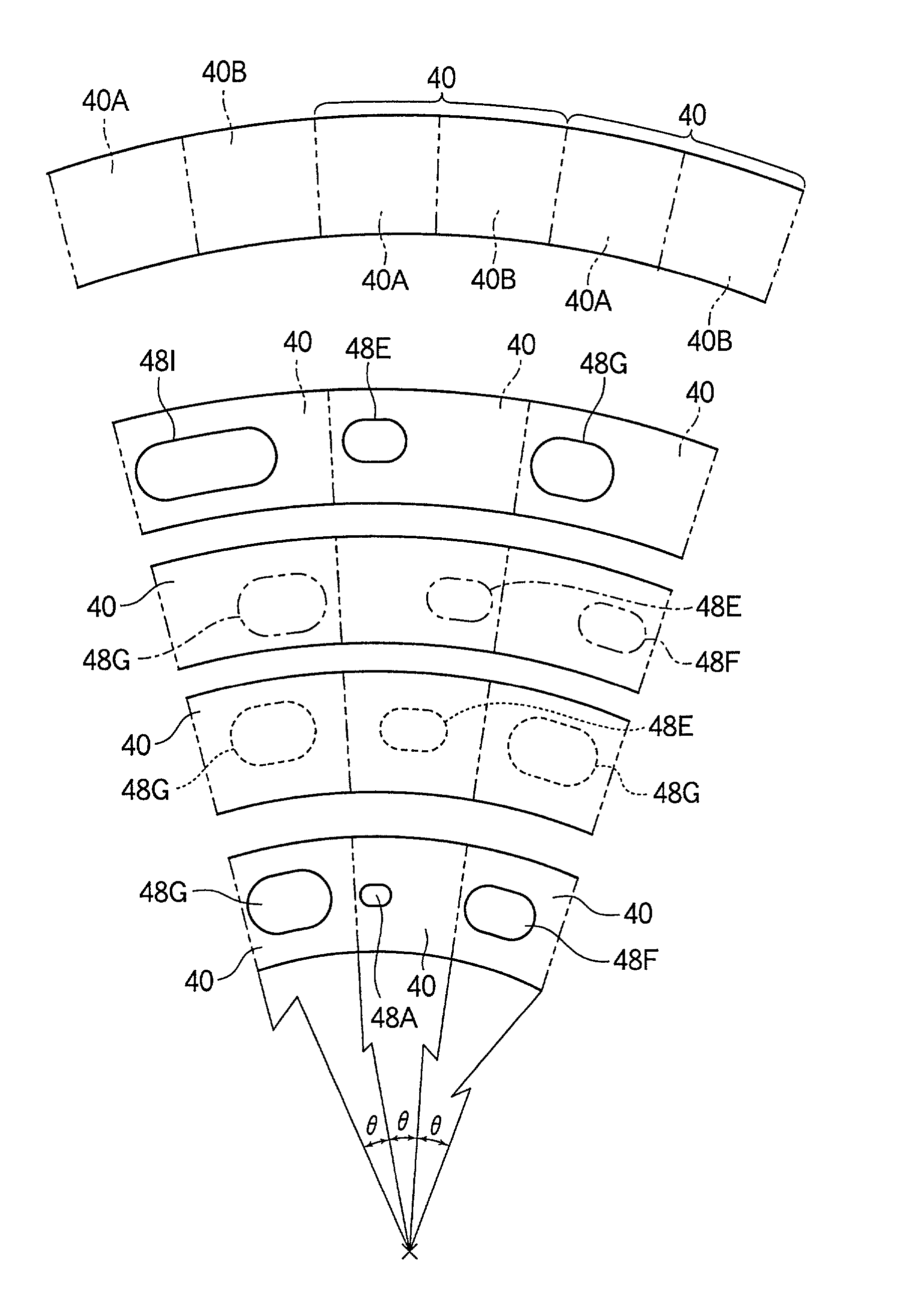
[0234]Now, the present invention is explained in conjunction with a comparative example with reference to examples in which the optical recording medium 10 according to the present invention has a constant angular velocity on the virtual recording cell 40.

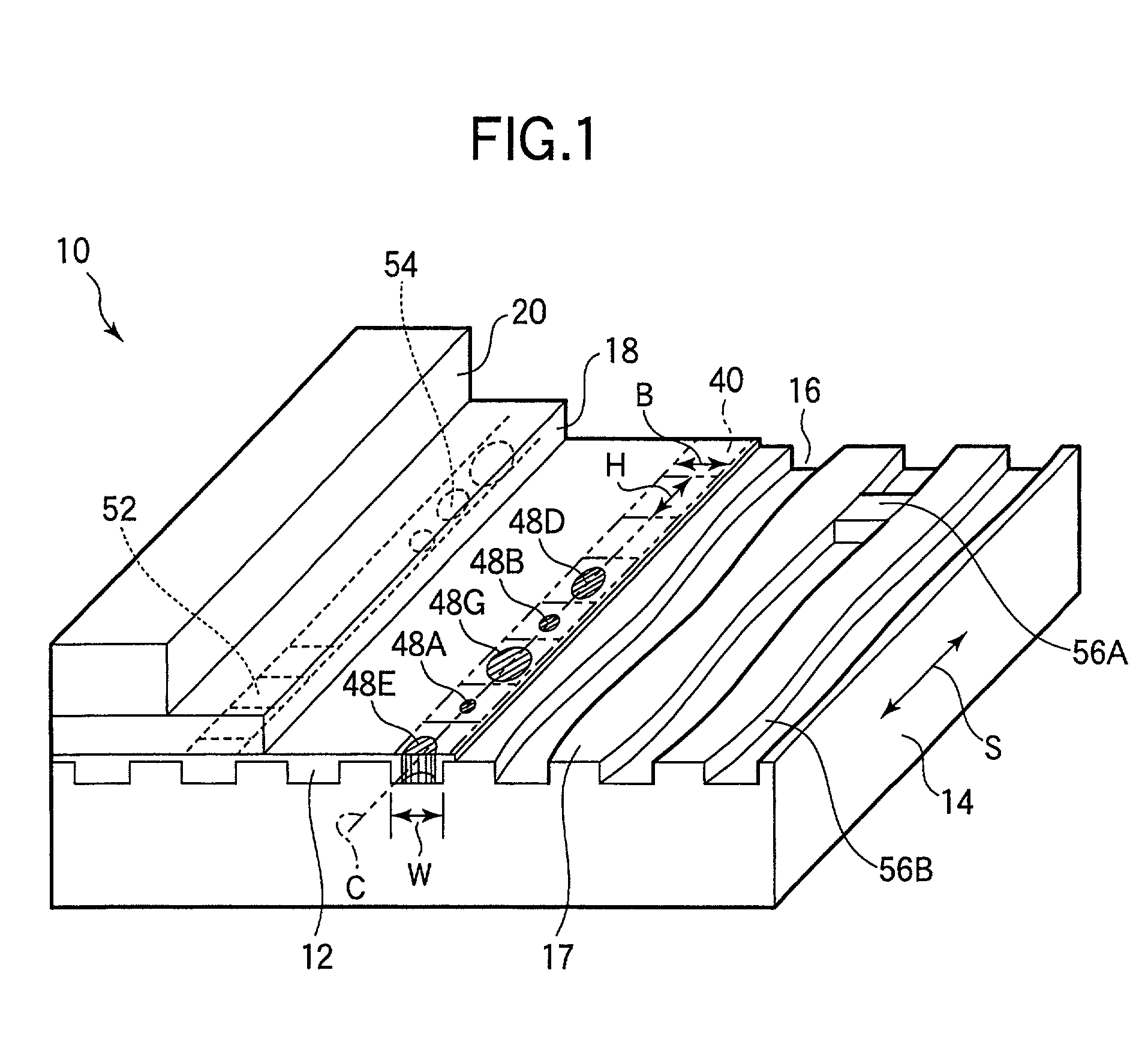
[0235]A CD-R was used here as the optical recording medium 10 which had the recording layer 12 made of a dye, and irradiation time was modulated to carry out a multi-level recording experiment in six stages (six and eight stages in Example 5) at radial positions of 25 mm and 50 mm.

[0236]The implementation conditions and results of Examples 1 to 7 and the comparative example were as shown in Table 1, and a high transfer rate and the reduction in access time were confirmed. Incidentally, the recording linear velocities in Examples 1 to 7 were 10.5 m / sec at a radius of 25 mm and 21.0 m / s at a radius of 50 mm at a constant angular velocity.

[0237]

TABLE 1Laserrecord-Cell lengthRotationaling(μm)velocitypowerAt 25AtJitter value (%)Example(...


PUM


Abstract

On a recording layer (12) of a disc-shaped optical recording medium (10), a plurality of virtual recording cells (40) are assumed contiguously in a spiral or concentric fashion in a groove (16). The irradiation time of the laser beam is modulated in five stages or more for each of the virtual recording cells (40) in response to information to be recorded, thereby forming recording marks (48A to 48G) of different sizes in five stages or more. The optical reflectivity of the virtual recording cell (40) is modulated in multi-stages to thereby vary the reflection level of a reading laser beam for reading operations in five stages or more. The length of the virtual recording cells (40) in the rotational direction of the disc is set to be equal to that of an arc having the same center angle with respect to the center of the disc.

Description

[0001]This application benifit of U.S. Provisional Application Ser. No. 60 / 279,748, filed Mar. 30, 2001, which claims benifit of U.S. Provisional Application Ser. No. 60 / 279,757, filed Mar. 30,2001, which claims benifit of U.S. Provisional Application Ser. No. 60 / 279,751, filed Mar. 30, 2001, which claims benifit of U.S. Provisional Application Ser. No. 60 / 279,750, filed Mar. 30, 2001, which claims benifit of U.S. Provisional Application Ser. No. 60 / 279,752, filed Mar. 30, 2001.DETAILED DESCRIPTION OF THE INVENTION[0002]1. Field of the Invention[0003]The present invention relates to an optical recording medium and an optical recording method for irradiating the optical recording medium with a laser beam by switching in multi-stages at least one of the irradiation time and the irradiation power of the laser beam in response to the data to be recorded in order to form recording marks of multiple types and thereby record information in multi-levels on the recording layer.[0004]2. Descr...

Claims


Application Information

Patent Timeline
IPC IPC(8): G11B15/52G11B7/00G11B7/0045G11B7/007G11B7/013G11B7/095G11B7/125G11B7/24
CPCG11B7/00456G11B7/00718G11B7/00745G11B7/24088G11B7/126G11B7/1267G11B7/0956G11B7/00736G11B7/24082
Inventor ARIOKA, HIROYUKITSUKAMOTO, SYUJIHORAI, TAKASHIOOTSUKI, SHIROU
Owner TDK CORPARATION
Why Eureka
Try Eureka