
Computed tomography dose indexing phantom selection for dose reporting

a computed tomography and phantom selection technology, applied in tomography, instruments, applications, etc., can solve problems such as concerns for patients on which it is utilized

Active Publication Date: 2006-07-25
GE MEDICAL SYST GLOBAL TECH CO LLC
View PDF11 Cites 28 Cited by
  • Summary
  • Abstract
  • Description
  • Claims
  • Application Information

AI Technical Summary

Benefits of technology

This approach enables more reliable and accurate CTDIvol reporting, minimizing radiation exposure while maintaining image quality by tailoring the imaging sequence to the specific patient and imaging region.

Problems solved by technology

Although CT scans provide a highly useful and critical medical diagnostic element, they must still be recognized to be a tool that, if improperly utilized, may pose concerns to the patients on which it is utilized.
The methodology operates through the use of gamma rays and x-rays which are only suitable for human exposure within limits.

Method used


Image

  • Computed tomography dose indexing phantom selection for dose reporting
  • Computed tomography dose indexing phantom selection for dose reporting
  • Computed tomography dose indexing phantom selection for dose reporting

Examples


Embodiment Construction

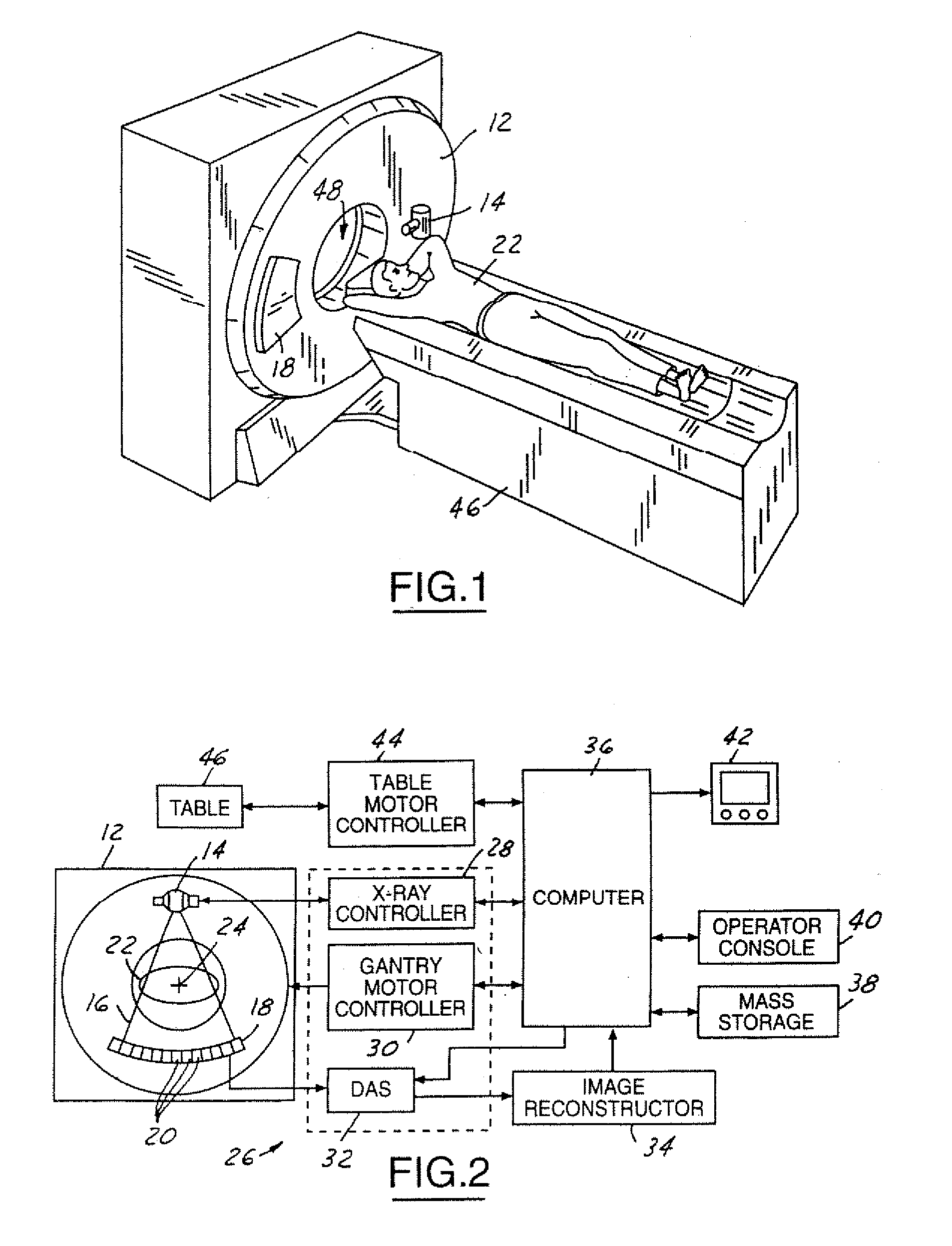
[0016]Referring now to FIGS. 1 and 2, which are illustrations of a computed tomography (CT) imaging system 10 for use with the detector assembly 18 of the present invention. Although a particular CT imaging system 10 has been illustrated, it should be understood that the detector assembly 18 of the present invention could be utilized in a wide variety of imaging systems. The CT imaging system 10 includes a scanner assembly 12 illustrated as a gantry assembly. The scanner assembly 12 includes an x-ray source 14 for projecting a beam of x-rays 16 toward a detector assembly 18 positioned opposite the x-ray source 14. The detector assembly 18 includes a plurality of detector elements 20, referred to as a detector array, which combine to sense the projected x-rays 16 that pass through an object, such as a medical patient 22. Each of the plurality of detector elements 20 produces an electrical signal that represents the intensity of an impinging x-ray beam and hence the attenuation of the...


PUM


Abstract

A computed tomography assembly is providing including an x-ray gantry assembly, an x-ray source projecting a beam of x-rays, a detector assembly positioned opposite the x-ray source and receiving the beam of x-rays, and a control mechanism in communication with the x-ray source and the detector assembly. The control mechanism includes logic adapted to: execute at least one scout scan of the object to produce a first scout scan image; generate an elliptical patient model based on the first scout scan image; match the elliptical patient model to a phantom diameter approximation; generate a dose report based on the phantom diameter approximation; and display said dose report on a display in communication with the control mechanism.

Description

BACKGROUND OF INVENTION[0001]The present invention relates generally to a computed tomography assembly, and, more particularly to a computed tomography assembly with improved phantom selection for dose reporting.[0002]Computed tomography has been utilized for a wide variety of imaging applications. One such category of applications is comprised of medical imaging. Although it is known that computed tomography may take on a wide variety of configurations within the medical industry, it commonly is based on the transmission of low energy rays through a body structure. These energy rays are subsequently received and processed to formulate an image, often three-dimensional, of the body structure that can by analyzed by clinicians as a diagnostic aid.[0003]The reception of energy rays, such as gamma rays or x-rays, is often accomplished through the use of a device referred to as a detector assembly. The detector assembly is typically comprised of a plurality of structures working in conc...

Claims


Application Information

Patent Timeline
Patent Type & Authority Patents(United States)
IPC IPC(8): H05G1/28
CPCA61B6/032A61B6/583A61B6/488A61B6/4035
Inventor TOTH, THOMAS LOUISHOFFMAN, DAVID MICHAEL
Owner GE MEDICAL SYST GLOBAL TECH CO LLC
Learn More