
Radio communication system, frequency allocation method and frequency allocation device

a radio communication system and frequency allocation technology, applied in the field of radio communication systems, can solve the problems of large interference from adjacent frequency bands (hereafter referred to as adjacent channel interference), large amount of adjacent channel interference, and large interference from adjacent frequency bands

Inactive Publication Date: 2006-07-25
NTT MOBILE COMM NETWORK INC
View PDF26 Cites 14 Cited by
  • Summary
  • Abstract
  • Description
  • Claims
  • Application Information

AI Technical Summary

Benefits of technology

[0037]The present invention has been achieved in view of the above-described considerations, and has the object of reducing the interference of leakage power generated between adjacent communication frequency bands of different businesses and to suppress large decreases in system capacity in cellular radio communication systems wherein specific frequency bands are allotted to a plurality of businesses.
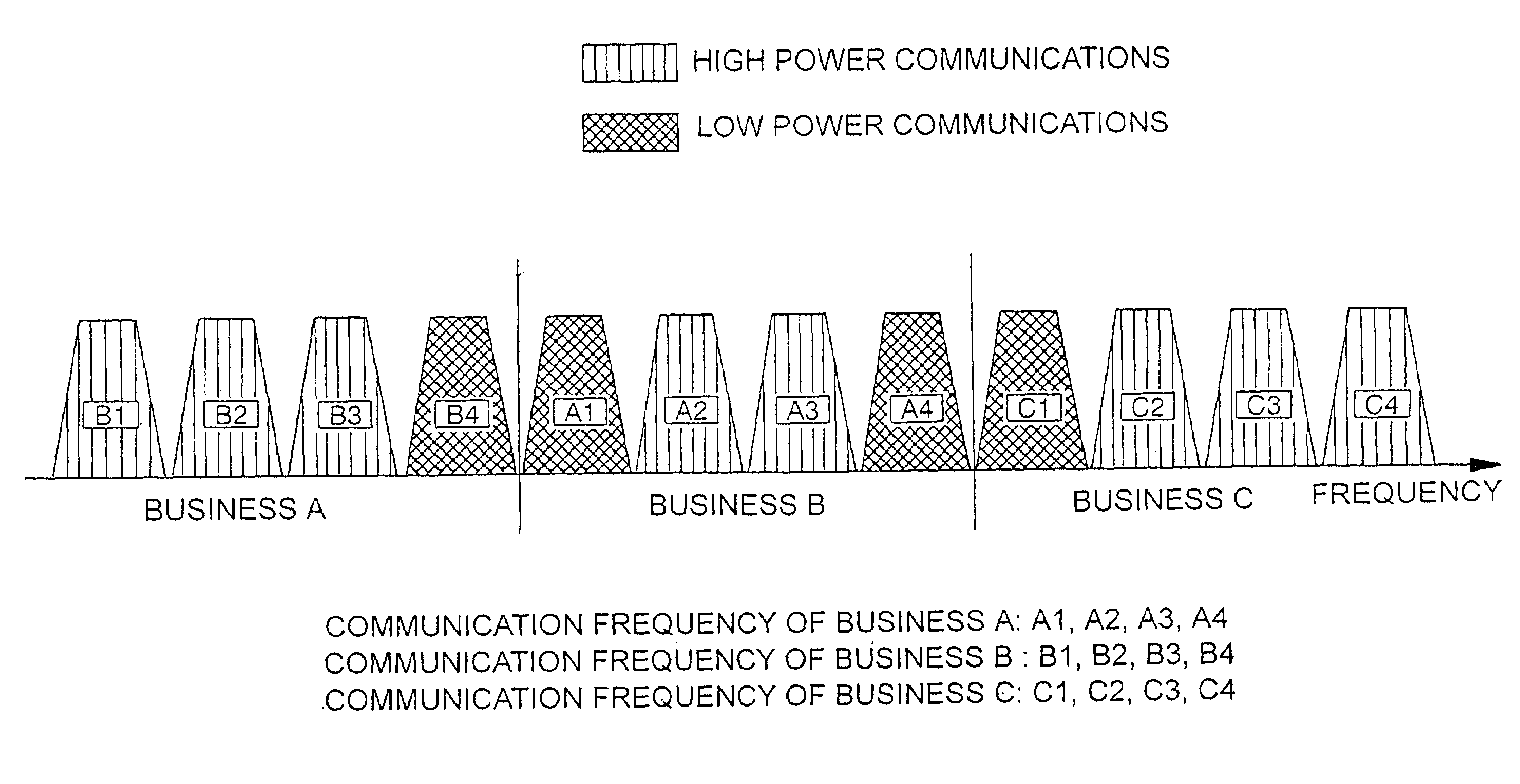
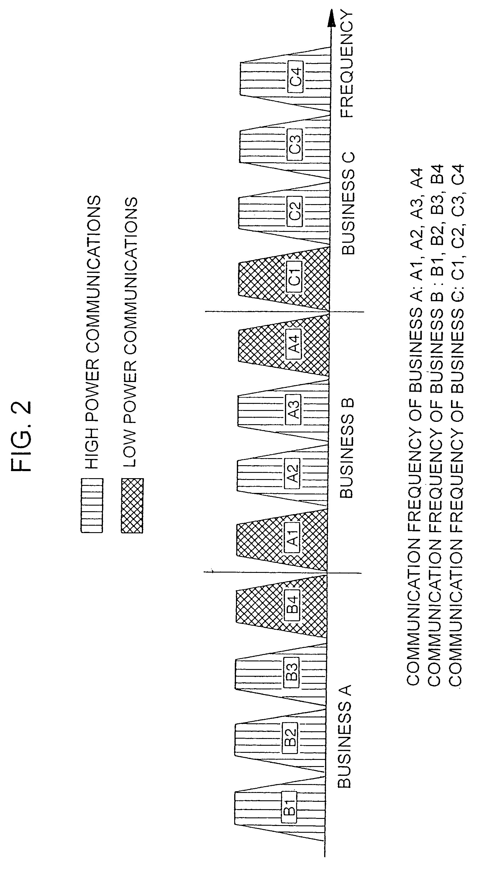
[0039]According to the present invention, non-adjacent frequency bands which are not adjacent to frequency bands allotted to other businesses are allotted to high power communications and adjacent frequency bands adjacent to frequency bands allotted to other businesses are allotted to low power communications, so as to enable reductions in the interference due to leaked power in channels which are adjacent between one business and another.

Problems solved by technology

However, unless the attenuation properties outside the bands of the reception filters are sufficient, the influence of interference from the adjacent frequency bands (hereafter referred to as adjacent channel interference) becomes large.
This adjacent channel interference causes reductions in the reception sensitivity and intermixture of noise in the mobile stations and base stations.
However, if the guard band B is narrow, then the amount of adjacent channel interference becomes large.
However, when a plurality of businesses offer mobile communication services in an overlapping service area, there are cases in which adjacent channel interference of a considerable interference level occurs between different businesses and this cannot be sufficiently suppressed even if transmission power control is performed by both the base stations and mobile stations adapted to the respective businesses.
In this case, even if the transmission power of the mobile station 30A is at maximum, there is a possibility that the effects of the adjacent channel interference due to the leakage signals from the mobile station 30A will not be able to be reduced.
Therefore, decreases in the system capacity due to adjacent channel interferences are manifested in increases in the proportion of parts of service areas in which a predetermined quality cannot be obtained or in increases in the proportion of time during which a predetermined quality cannot be obtained at the same location.

Method used


Image

  • Radio communication system, frequency allocation method and frequency allocation device
  • Radio communication system, frequency allocation method and frequency allocation device
  • Radio communication system, frequency allocation method and frequency allocation device

Examples


first embodiment

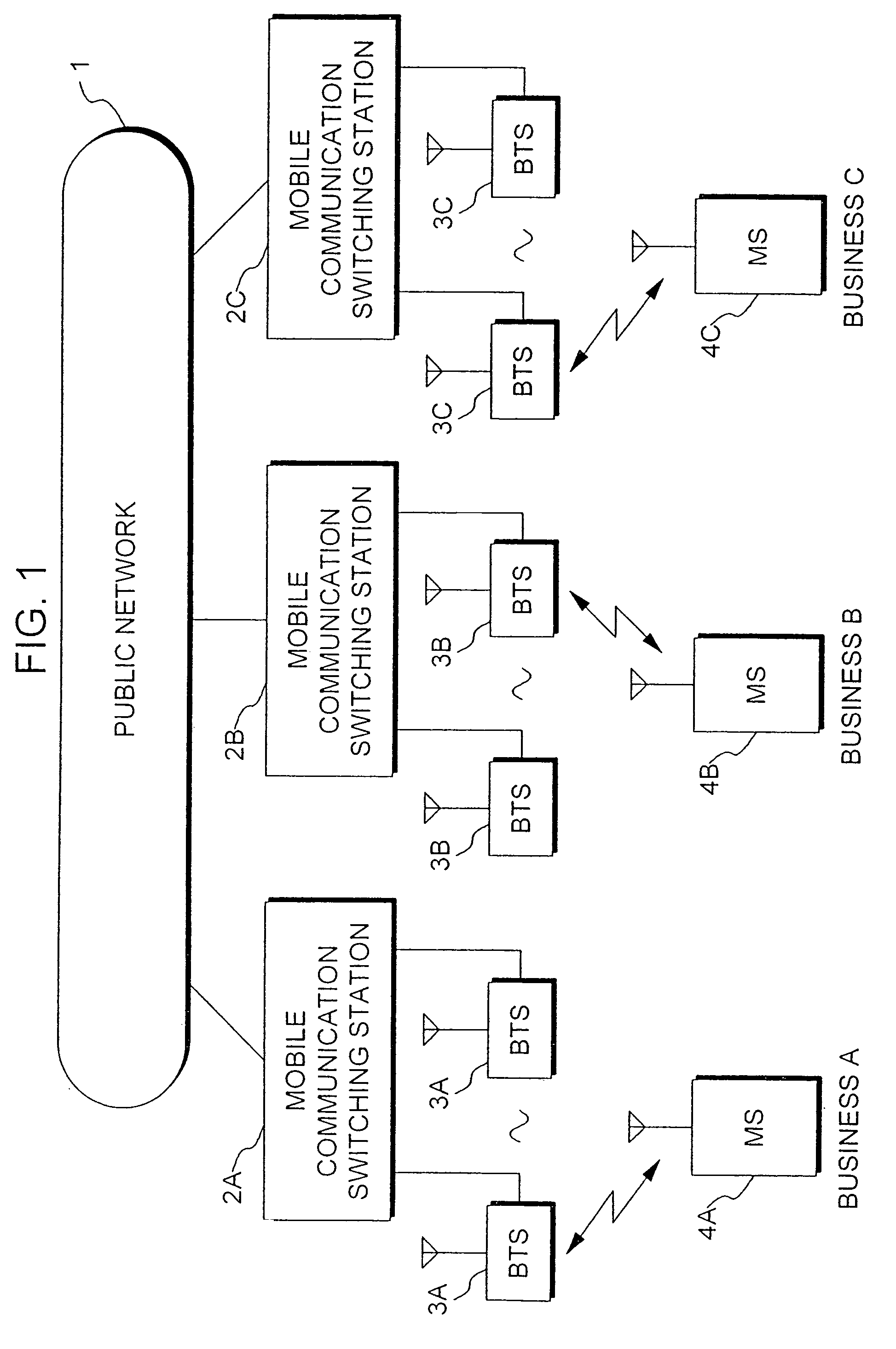
[0057]FIG. 1 is a diagram showing the structure of a radio communication system according to the present invention. In this radio communication system, businesses A, B and C offer mobile communication services. Additionally, this radio communication system is a CDMA (Code Division Multiple Access) mobile communication system.

[0058]In FIG. 1, mobile communication switching station 2A and base station 3A are communication installations for business A, mobile communication switching station 2B and base station 3B are communication installations for business B and communication switching station 2C and base station 3C are communication installations for business C. Although each business has many base stations and mobile communication switching stations aside from those shown in the drawings, these are not shown in the drawings in order to prevent the drawings from becoming overcrowded.

[0059]Additionally, in FIG. 1, mobile station 4A is the mobile station of a user contracted with busin...

fourth embodiment

[0106]Next, a frequency allocation method in a radio communication system according to the present invention shall be explained.

[0107]Generally speaking, in voice communications in digital mobile communications, the voice data are compressed and sent at a low data rate so as not to obstruct bi-directional real-time conversation. Additionally, since a large code error occurs in digital mobile communications in comparison to wired communications, it is necessary to perform error correction coding on the compressed voice data. For this reason, the transmission quality, e.g. the values demanded for the code error rate must be set relatively weakly (e.g. BER (Bit Error Rate)=1×10⁻³).

[0108]Additionally, in packet communications, the data are divided into small blocks, and each block is transmitted via a radio channel, with retransmission control being performed when there is an error in a block. For this reason, when transmitting with a comparatively high error rate, or when an interrupti...


PUM


Abstract

Among cellular radio communication systems, there are those in which a plurality of businesses, e.g. businesses A, B and C share a designated frequency band, and each business provides radio communication services using respectively allotted frequency bands. In this type of radio communication system, there are cases in which mobile stations belonging to different businesses use channels which have adjacent frequencies, in which case adjacent channel interference of a large interference level is produced. Therefore, in this radio communication system, of the frequency bands allotted to each business, the adjacent frequency bands which are adjacent to frequency bands allotted to other businesses are allotted to low power communications, while non-adjacent frequency bands which are not adjacent to frequency bands allotted to other businesses are allotted to high power communications.

Description

PRIORITY AND CROSS REFERENCE TO RELATED APPLICATION[0001]This is a continuation of U.S. application Ser. No. 09 / 446,295 filed Dec. 17, 1999 (U.S. Pat. No. 6,658,257), which is incorporated by reference herein in its entirety.TECHNICAL FIELD[0002]The present invention relates to a radio communication system composed of the communication equipment of a plurality of different businesses, and a frequency allocation method and frequency allocation device therefor.BACKGROUND ART[0003]Cellular radio communication systems are generally used as mobile phone systems due to their ability to cover wide service areas. In these cellular radio communication systems, a plurality of base stations are arranged in a service area separately, and these base stations form a multitude of cells (zones) for covering the entire service area without gaps. In these cells, mobile stations can communication with other parties by using base stations.[0004]Businesses which offer this type of mobile communication s...

Claims


Application Information

Patent Timeline
IPC IPC(8): H04Q7/20H04W16/14
CPCH04W16/14H04W28/04H04W72/082H04W72/0453H04W28/22Y02D30/70H04W72/541
Inventor HIRAYAMA, TOMOAKITAKAMI, TADAONAGATA, KIYOHITO
Owner NTT MOBILE COMM NETWORK INC
Learn More