System and method for simultaneous construction of physical and CAD models

a technology of cad and system, applied in the field of computer-aided design, can solve the problems of inability to track or measure certain corners of the physical model, inability to physically access the load-bearing walls of the atrium, and inability to achieve the effect of measuring the load-bearing walls,

Inactive Publication Date: 2006-07-25
IBM CORP
View PDF14 Cites 26 Cited by
  • Summary
  • Abstract
  • Description
  • Claims
  • Application Information

AI Technical Summary

Problems solved by technology

With currently available CAD systems, architects must rely on the use of a 2-D display, a mouse-driven cursor, and keyboard entry to create 3D (three-dimensional) CAD models, which is a very tedious process.
It is sometimes not possible, however, to track or measure certain corners of the physical model because they may be inside the physical model and, thus, inaccessible after the model has been built.
For example, an atrium entrance lobby might be included in the scale model of a building, but the interior, load-bearing walls of the atrium may not be physically accessible for measurement because an entry facade may be in the way.
Therefore, in such situations, the architect may not be able to generate a CAD model that accurately corresponds to the physical model without having to disassemble the physical model to measure the inaccessible corners, and then assemble the parts and repeat the process.

Method used


Image

  • System and method for simultaneous construction of physical and CAD models
  • System and method for simultaneous construction of physical and CAD models
  • System and method for simultaneous construction of physical and CAD models

Examples


Embodiment Construction

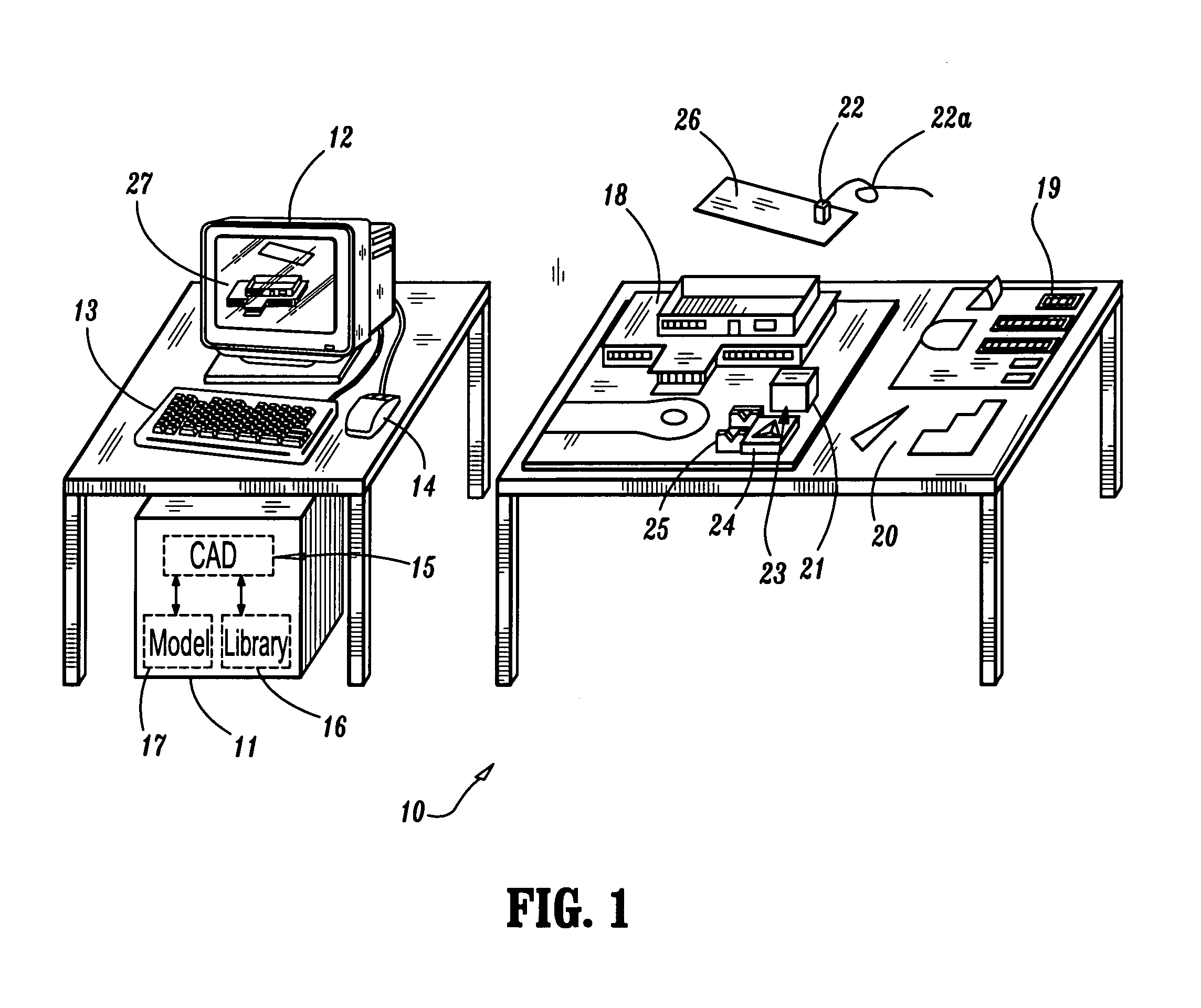
[0029]Referring now to FIG. 1, a schematic diagram illustrates a system according to an embodiment of the present invention for simultaneously constructing a corresponding physical model and CAD model. The system 10 comprises a data processing device 11 (e.g., a personal computer), a graphics display unit (monitor) 12, and one or more input devices such as a keyboard 13 and a pointing device 14 (e.g., a mouse, trackball, spaceball, etc.). The data processing device 11 comprises memory and at least one processor for storing and executing a CAD application 15 which, in accordance with the present invention, dynamically builds and stores a CAD model 17 of a corresponding physical structure 18 as the physical structure 18 is constructed. The CAD application 15 processes graphics data (or pixel data) representing the CAD model 17, which is output to the display unit 12 for displaying the current state of the CAD model (as denoted by reference numeral 27) during construction of the physic...


PUM


Abstract

A system and method for simultaneous construction of a corresponding CAD model and physical model, wherein the CAD model comprises a plurality of CAD representations each corresponding to a physical component part that is used to construct the physical model. During construction of a physical model using individual component parts, the CAD system can identify a given component part and retrieve its CAD representation from a CAD library. In addition, the CAD system allows the user to build a CAD representation of a given component part if its CAD representation is not stored in the CAD library. After the CAD representation of the component part is generated, the CAD system will track the motion (position and orientation) of the part as it is maneuvered into a desired position in the physical model. The position and orientation, as well as the CAD representation of the component part as it exists in the physical model is saved in a CAD model database. During assembly, the CAD system can render an image of the CAD model as each component part is placed in the physical model.

Description

BACKGROUND[0001]1. Technical Field[0002]The present application relates generally to computer-aided design (CAD) and, in particular, to a system and method for simultaneously constructing a CAD model and a corresponding physical model, wherein the CAD model comprises a plurality of CAD representations each corresponding to one of the component parts that are used to construct the physical model.[0003]2. Description of Related Art[0004]Conventionally, architects and other mechanical designers are accustomed to building a physical scale model of their intended design before generating a CAD model corresponding to the physical model. For instance, when designing a commercial or public project, an architect will typically construct a physical scale model before creating a CAD model for developing construction plans and for laying out the floor plans of offices and other rooms. The physical model is typically constructed using a combination of standard parts such as standard size wall pa...

Claims


Application Information

Patent Timeline
Patent Type & Authority Patents(United States)
IPC IPC(8): G06G7/34G06F17/50G06F19/00
CPCG06F17/50G06F30/00
Inventor WOLFE, JR., ROBERT H.
Owner IBM CORP
Why Eureka
Try Eureka