
Shale gas reservoir crustal stress logging prediction method based on rock physics model

A petrophysical model and prediction method technology, applied in seismology for logging records, etc., can solve problems such as not considering kerogen, not suitable for shale gas reservoirs, etc., and achieve the effect of improving accuracy

Inactive Publication Date: 2014-05-14
CHINA UNIV OF PETROLEUM (BEIJING)
View PDF5 Cites 75 Cited by
  • Summary
  • Abstract
  • Description
  • Claims
  • Application Information

AI Technical Summary

Problems solved by technology

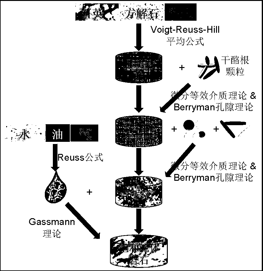
Shale gas reservoirs have complex lithology, various microscopic pore types, and rich kerogen. For such unconventional reservoirs, conventional petrophysical models cannot calculate more accurate velocities. The classic Xu-White model (see Reference Reference 2), mixing sandstone and clay, using two-dimensional Kuster- model (see Ref. 6) for the elastic modulus of dry rock with porosity and for fluid-saturated rock using the Gassmann (ref. 10) equation, but this model only The properties are not complicated, and the pore types are relatively simple; the Xu-Payne rock physics model (see reference 7) and the DEM-Gassmann rock physics model (see reference 3) developed on this basis both use the 3D pore spectrum to calculate The bulk modulus and shear modulus of pore-type rocks get better results, but these two models are only suitable for relatively simple lithology, and neither of them considers kerogen, so they are not suitable for shale gas reservoirs
Bandyopadhyay et al. (see reference 8) used the Brown-Korriga (see reference 4) model to calculate the elastic modulus of rocks containing kerogen by means of solid replacement. However, according to core observations, kerogen is dispersed in a certain particle form In shale, this method does not simulate the real state of organic matter in the rock

Method used


Image

  • Shale gas reservoir crustal stress logging prediction method based on rock physics model
  • Shale gas reservoir crustal stress logging prediction method based on rock physics model
  • Shale gas reservoir crustal stress logging prediction method based on rock physics model

Examples


specific Embodiment approach

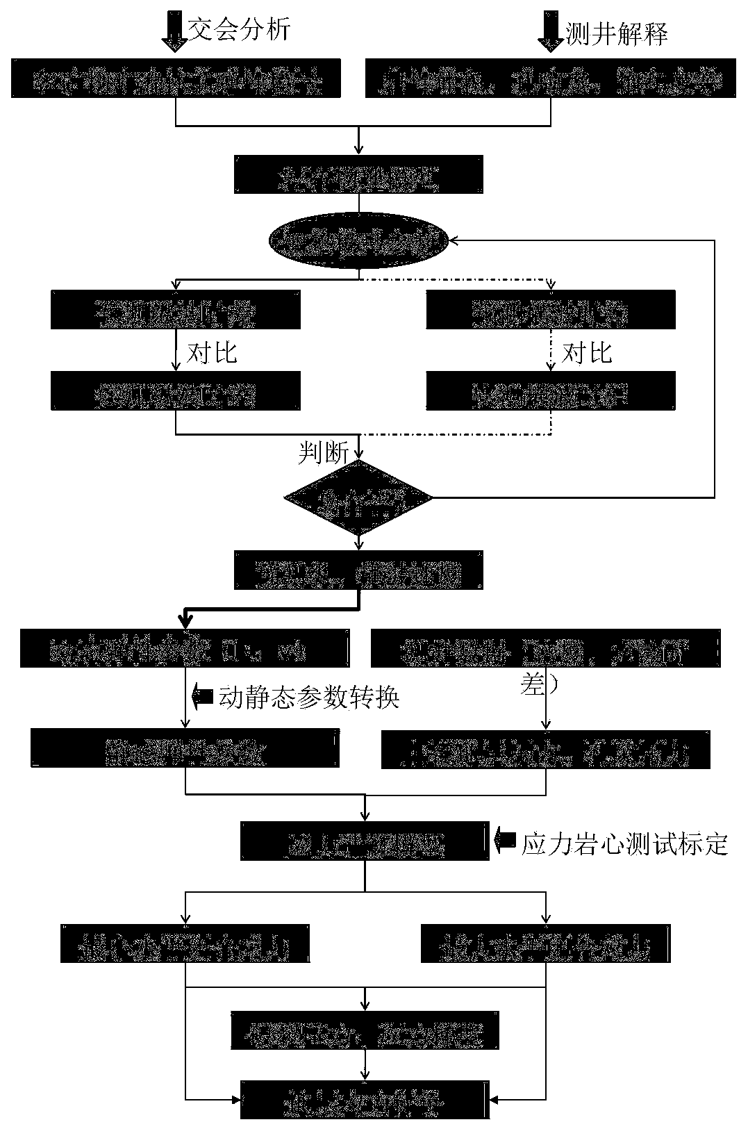
[0024] Such as figure 1 Shown is the flow chart of the method for predicting in-situ stress logging in shale gas reservoirs based on petrophysical models. First, the mineral volume, porosity, saturation, and kerogen volume in the formation are obtained through logging interpretation; and obtained through rendezvous analysis The elastic modulus and density of the main minerals. The elastic modulus and density of the fluid are obtained through literature research. The elastic parameters here specifically refer to the bulk modulus and shear modulus; the logging interpretation results are introduced into the newly established shale gas reservoir The petrophysical model, by adjusting the pore type distribution spectrum parameters in the petrophysical model, iteratively calculates the longitudinal wave velocity and the shear wave velocity. Use the predicted longitudinal and transverse wave velocities to calculate the dynamic Young's modulus and Poisson's ratio, and convert the dynamic...


PUM


Abstract

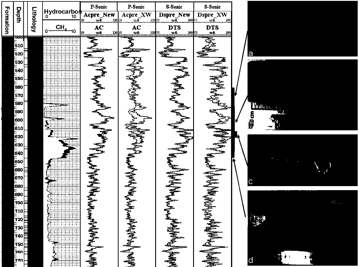
The present invention relates to a shale gas reservoir crustal stress logging prediction method based on a rock physics model. According to the method, a shale gas reservoir rock physics model which takes kerogen particles into consideration is established, so as to predict a longitudinal and transverse wave velocity of the logging; based on the above, a maximum and minimum horizontal principal stress and a fracture pressure of the reservoir are calculated; and an accurate stress assessment of a shale gas reservoir is carried out while a transverse wave logging is not provided. The beneficial effects of the invention are that: the rock physics model in line with characteristics of the shale gas reservoir is established to improve precision of the prediction velocity; and based on the rock physical model, the maximum and minimum horizontal principal stress and the fracture pressure are obtained, so that while the measured transverse wave logging data are not provided, the underground stress can be predicted on the basis of a conventional logging curve, and the prediction result is high in accuracy.

Description

Technical field [0001] The invention belongs to the field of in-situ stress logging prediction of shale gas reservoirs, and in particular relates to a shale gas reservoir in-situ stress logging prediction method based on a petrophysical model. Background technique [0002] For shale gas reservoirs, since fracturing reforms directly affect gas production, the prediction of underground stress determines the quality of fracturing reforms. There are many well-logging evaluation models for reservoir in-situ stress, the more mature ones are Mohr Coulomb model, Huang Rongzun model (see Reference 1), uniaxial strain model, etc. Through these models to obtain the maximum and minimum horizontal principal stresses, and then to obtain the fracture pressure, stress gradient, etc., the reservoir can be evaluated; but the application of these models must be based on the more accurate Young's modulus, Poisson's ratio and other rock mechanics Parameters are used as input parameters, and accurate...

Claims


Application Information

Patent Timeline
IPC IPC(8): G01V1/40
Inventor 刘致水孙赞东
Owner CHINA UNIV OF PETROLEUM (BEIJING)
Learn More