Video-supported planning of equipment installation and/or room design

Inactive Publication Date: 2006-11-21
SIEMENS CORP
View PDF15 Cites 74 Cited by
  • Summary
  • Abstract
  • Description
  • Claims
  • Application Information

AI Technical Summary

Problems solved by technology

The problem is constrained by the fact that a MRI machine produces a strong magnetic field and that no metallic equipment should be within its reach.

Method used


Image

  • Video-supported planning of equipment installation and/or room design
  • Video-supported planning of equipment installation and/or room design
  • Video-supported planning of equipment installation and/or room design

Examples


Embodiment Construction

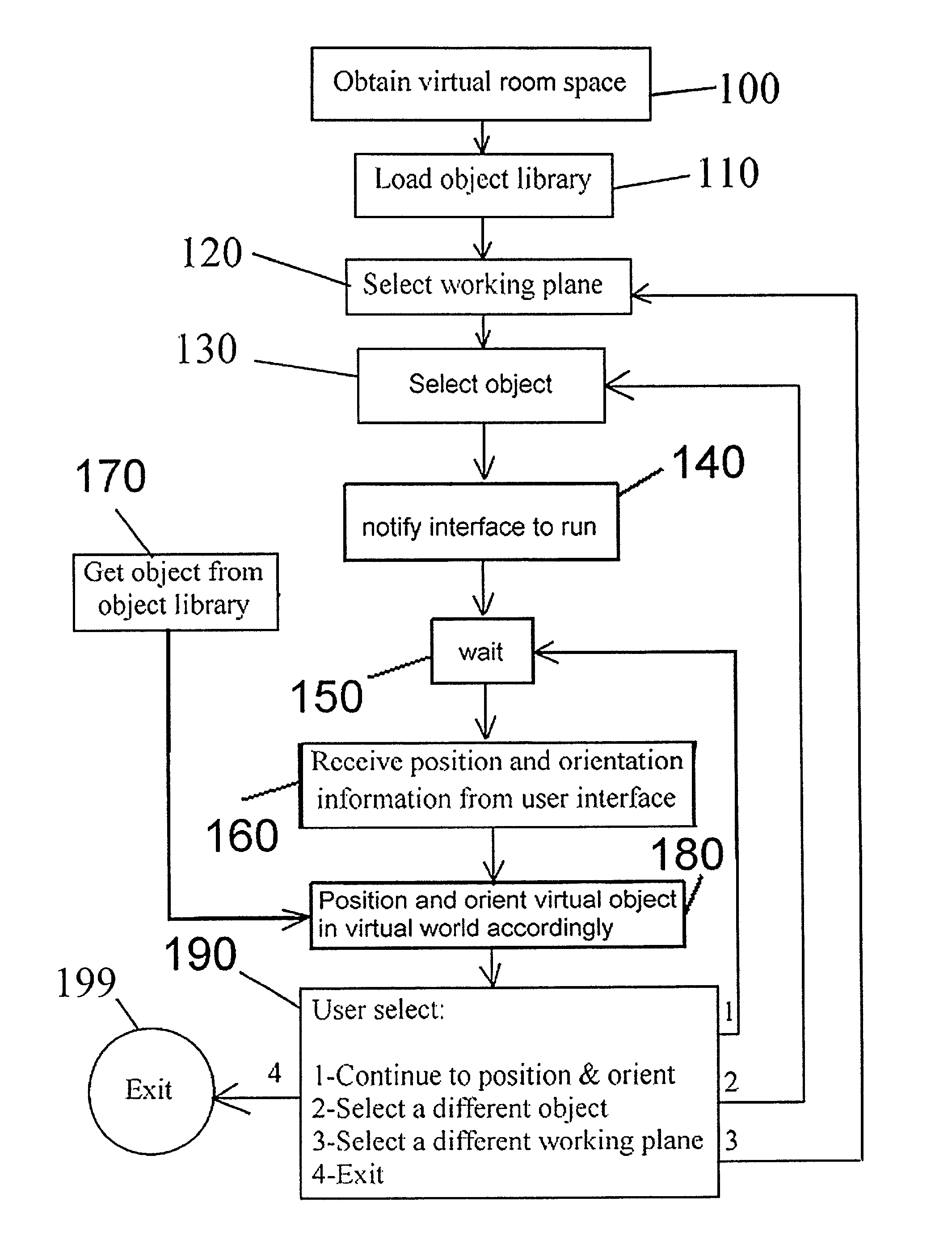
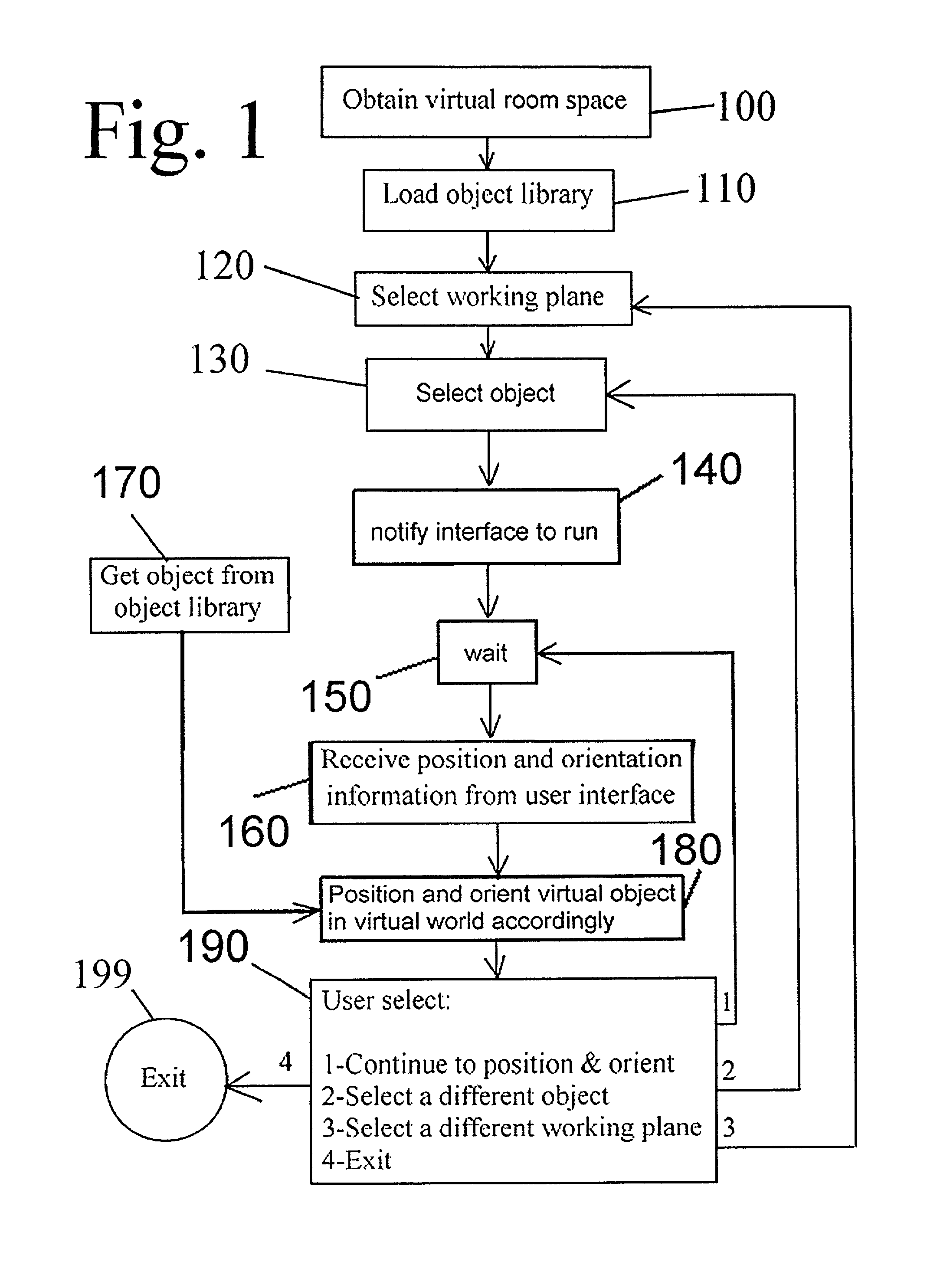
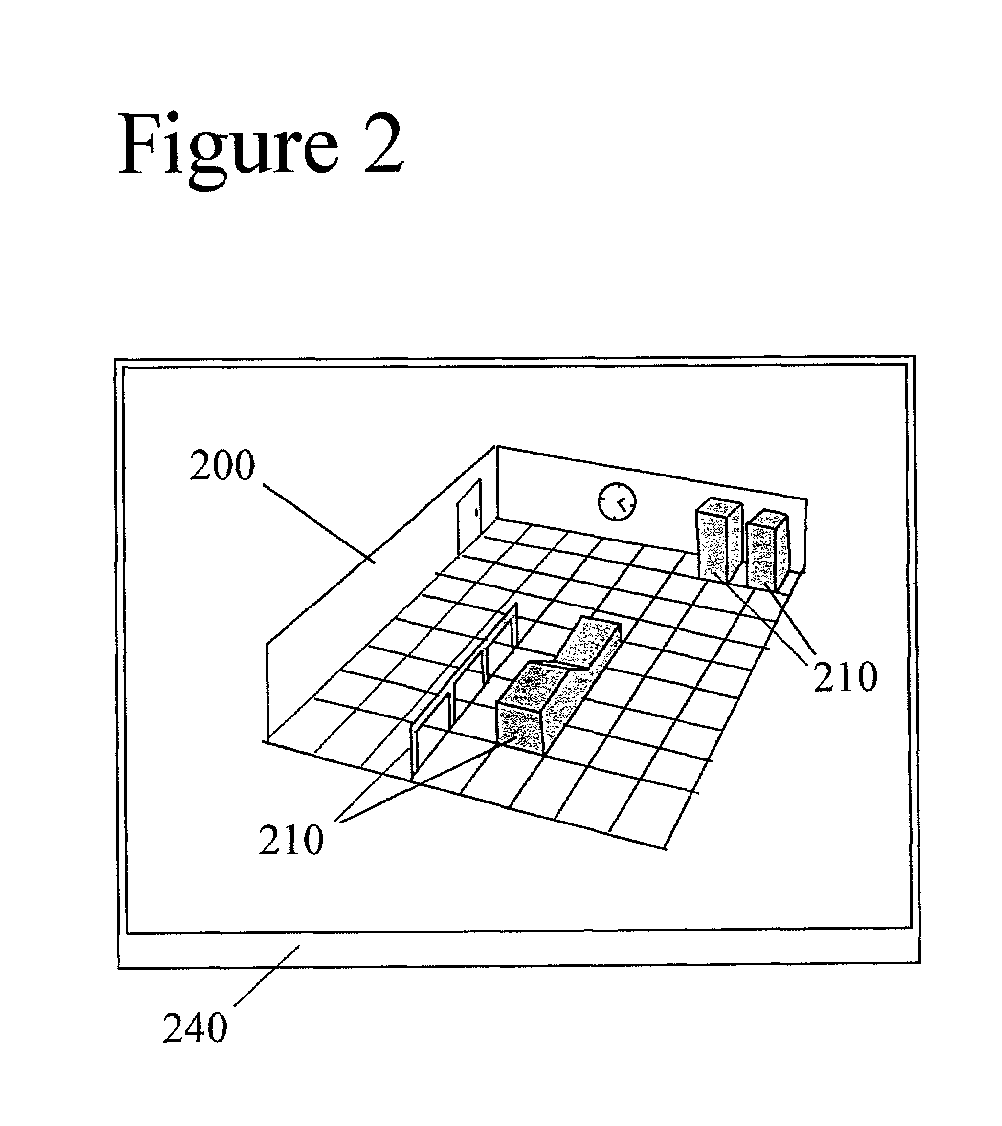
[0024]Referring to FIGS. 1 and 2, there is shown a flowchart of a preferred embodiment of the invention, which begins with preferably a 3D virtual representation of the physical room, though the methods of this invention may be applied to simple 2D floor plan representations. When starting up, the current state of the physical room or of the room design is displayed on a display device, generally a computer monitor. A typical display is shown in FIG. 2. This might include walls, steel construction, etc. The user of the system might be a design engineer, a plant designer, a maintenance planner, a room planner, a planner of the installation of new equipment in a room, etc. The user needs to add various virtual objects (for instance pieces of equipment) to the virtual representation of the room space until the room (new or updated) design is complete. Several users can also use the system simultaneously. Our system is a collaborative user interface that helps the user(s) better visuali...


PUM


Abstract

Disclosed is a room planning and design system, comprising a virtual room space comprising a virtual representation of a physical room space, an object library of virtual objects, said virtual objects comprising virtual representations of equipment, machines and objects that may be placed in a room, a user interface comprising a first user interface component for selecting said virtual objects from said virtual library and positioning them in said virtual room space, a second user interface component for manipulating the positions and orientations of said virtual objects within said virtual room space, a workspace comprising a physical model of said physical room space, physical marker objects substantially scaled to said workspace for manual placement and orientation of said markers objects in said workspace, one or more detectors for detecting information regarding the positioning of said marker objects in said workspace and transmitting said information to a visualization module, and said visualization module adapted to receive said information from said detectors and utilize said information for positioning said virtual objects within said virtual room space.

Description

CROSS-REFERENCE TO RELATED APPLICATIONS[0001]This patent application is based upon, and claims the benefit of, Provisional U.S. Patent No. 60 / 245,149, entitled VIDEO-SUPPORTED VIRTUAL PLANT DESIGN (VPA), filed Nov. 3, 2000, the disclosures of which are incorporated by reference herein in their entirety.FIELD OF THE INVENTION[0002]This invention relates to computer-assisted installation of equipment in rooms.BACKGROUND OF THE INVENTION[0003]Buyers and / or suppliers of equipment need to plan where to put said equipment in their existing / new / in-planning facilities. For instance, during the construction of manufacturing plants, and after the civil construction of the plant building is already completed, the design engineer plans the positioning of the many components of the factory (manufacturing machines, storage areas, . . . ), within the physical constraints imposed by the completed structure. Another example is the installation of MRI (magnetic resonance imaging) machines in hospital...

Claims


Application Information

Patent Timeline
Patent Type & Authority Patents(United States)
IPC IPC(8): G06F17/50G06F3/00G06F3/01G06F3/033G06F3/042G06T19/00
CPCG06F3/011G06F3/0354G06F3/042G06F3/0425G06T19/00G06T2210/04
Inventor BASCLE, BENEDICTERUGE, THOMASRACZYNSKI, ARTUR
Owner SIEMENS CORP
Why Eureka
Try Eureka