Method and arrangement for the comparison of technical system by means of system replacements

a technology of system replacement and comparison method, applied in the direction of specific program execution arrangement, program control, testing/calibration of speed/acceleration/shock measurement device, etc., can solve the problem of not being able to meet the requirements of any environment of the technical system, and achieve the effect of loss of precision

Inactive Publication Date: 2006-07-25
ONESPIN SOLUTIONS
View PDF3 Cites 6 Cited by
  • Summary
  • Abstract
  • Description
  • Claims
  • Application Information

AI Technical Summary

Benefits of technology

[0024]A first advantageous configuration of the method in accordance with the present invention is characterized in that the environment of the two technical systems being compared is restricted, by monitoring these for values potentially appearing at their outputs and by reducing the environment by such input values, which entail an output value, which cannot be generated by the other system under any circumstances.
[0030]It is important and advantageous in this case that, despite said replacements, no loss of precision is introduced in the comparison.
[0031]The basic idea of the invention, therefore, is to reduce a comparison of two technical systems which according to conventional opinion is not possible to a substantially simpler, technically achievable comparison in which part systems of one or both systems are specifically replaced. The replacements are performed in a controlled manner by monitoring a replacement condition with constraints. The monitoring of the replacement condition just as the generation and monitoring of the necessary constraints occur automatically. A comparison of both systems can thus be carried out based on the replacements of the part systems, without introducing a loss of precision in the comparison.

Problems solved by technology

a) automatic monitoring as to whether the first technical system can be replaced by the replacement system with a replacement condition, according to which it is not possible for any environment of the technical systems to find a functional difference between the first technical system and the replacement system when the respective interfaces are accessed.
b) otherwise automatic constraint of the behaviour of the environment of both systems and renewed monitoring of the replacement condition with the restricted environment,

Method used


Image

  • Method and arrangement for the comparison of technical system by means of system replacements
  • Method and arrangement for the comparison of technical system by means of system replacements

Examples


Embodiment Construction

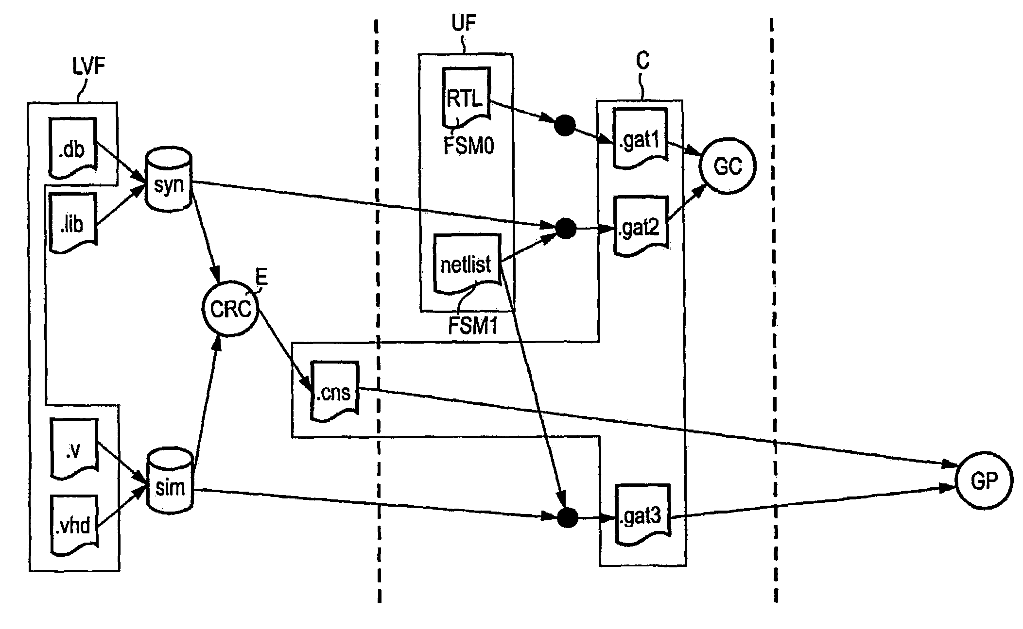
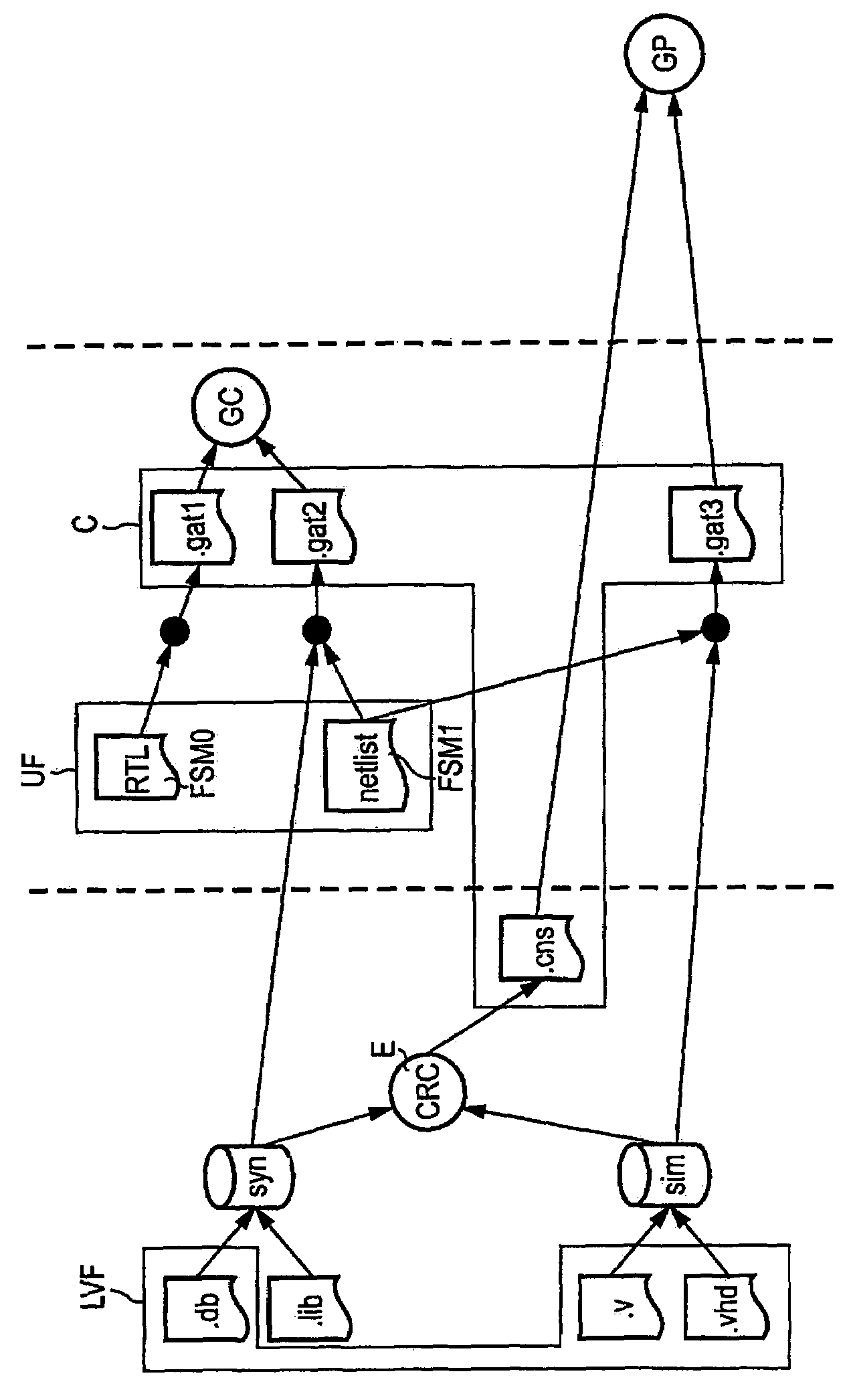
[0035]Firstly, for this purpose, the replacement condition E (safe replaceability) of technical systems is dealt with in greater detail. Such a replacement condition E for a technical system, which is represented by finite state systems (FSMs), has already been defined in “Pixley, Carl; Singhal, Vigyan; Aziz, Adnan; Brayton, Robert K.: multi-level synthesis for safe replaceability; ICCAD94, pages 442–449, 1994”.

[0036]Further basic principles are evident from:

[0037]Hasteer, Gagan; Mathur, Anmol; Banerjee, Prithviraj: an implicit algorithm for finding steady states and its application to FSM verification; DAC98, pages 611–614, 1998.

[0038]Singhal, Vigyan; Pixley, Carl: the verification problem for safe replaceability, CAV94, pages 311–323, 1994.

[0039]Singhal, Vigyan; Pixley, Carl; Rudell, Richard L; Brayton, Robert K.: the validity of retiming sequential circuits. DAC95, pages 316–321, 1995.

[0040]The definition presented below extends the term of replaceability to replaceability with c...


PUM


Abstract

The invention permits a comparison of two technical systems, which according to conventional opinion is not possible to carry out, based on a substantially simpler, technically achievable comparison, in which part systems of one or both systems are specifically replaced. The replacements are performed in a controlled manner by monitoring a replacement condition with constraints. The monitoring of the replacement condition and the generation and monitoring of the necessary constraints occur automatically. A comparison of both systems can thus be carried out based on the replacement of the part systems without introducing a loss of precision in the comparison.

Description

BACKGROUND OF THE INVENTION[0001]1. Field of the Invention[0002]The invention relates to a method for the comparison of technical systems to check functional equivalence by means of system replacements.[0003]2. Description of Related Art[0004]As is known, even minor internal behaviour differences can easily lead to failure in the comparison of technical systems, in particular if large and complex systems are concerned.[0005]In the case of such larger technical systems as, for instance, Application Specific Integrated Circuits (ASICs), at present there is no durable and satisfactory method of solving this problem.[0006]Depending on the particular scope of application, there are a few known ideas to solve this problem.[0007]A possible scenario, in which the above problem can occur, is implementation verification, when the synthesis results are to be compared to the synthesis inputs, in order to ensure that the synthesis process has not introduced any modifications into the functionali...

Claims


Application Information

Patent Timeline
Patent Type & Authority Patents(United States)
IPC IPC(8): G06F17/50
CPCG06F17/504G06F30/3323
Inventor HORETH, STEFANWARKENTIN, PETER
Owner ONESPIN SOLUTIONS
Why Eureka
Try Eureka