Climate control systems and methods

Inactive Publication Date: 2016-01-14
SURNA
View PDF0 Cites 7 Cited by
  • Summary
  • Abstract
  • Description
  • Claims
  • Application Information

AI Technical Summary

Benefits of technology

[0007]Provided herein are systems and methods for controlling climate in an enclosed space, such as

Problems solved by technology

This can significantly increase costs, especially during the summer when electricity demand on the grid is highest, often resulting in a corresponding increase in cost for cooling.
Greenhouses, the largest of indoor agricultural facilities, often suffer from the inability to properly control humidity, therefore providing prime conditions for many molds and other harmful organisms to grow.
Often times, the largest of g

Method used


Image

  • Climate control systems and methods
  • Climate control systems and methods
  • Climate control systems and methods

Examples


example 1

Method of Quad-Generation for Control of an Indoor Agricultural Plant

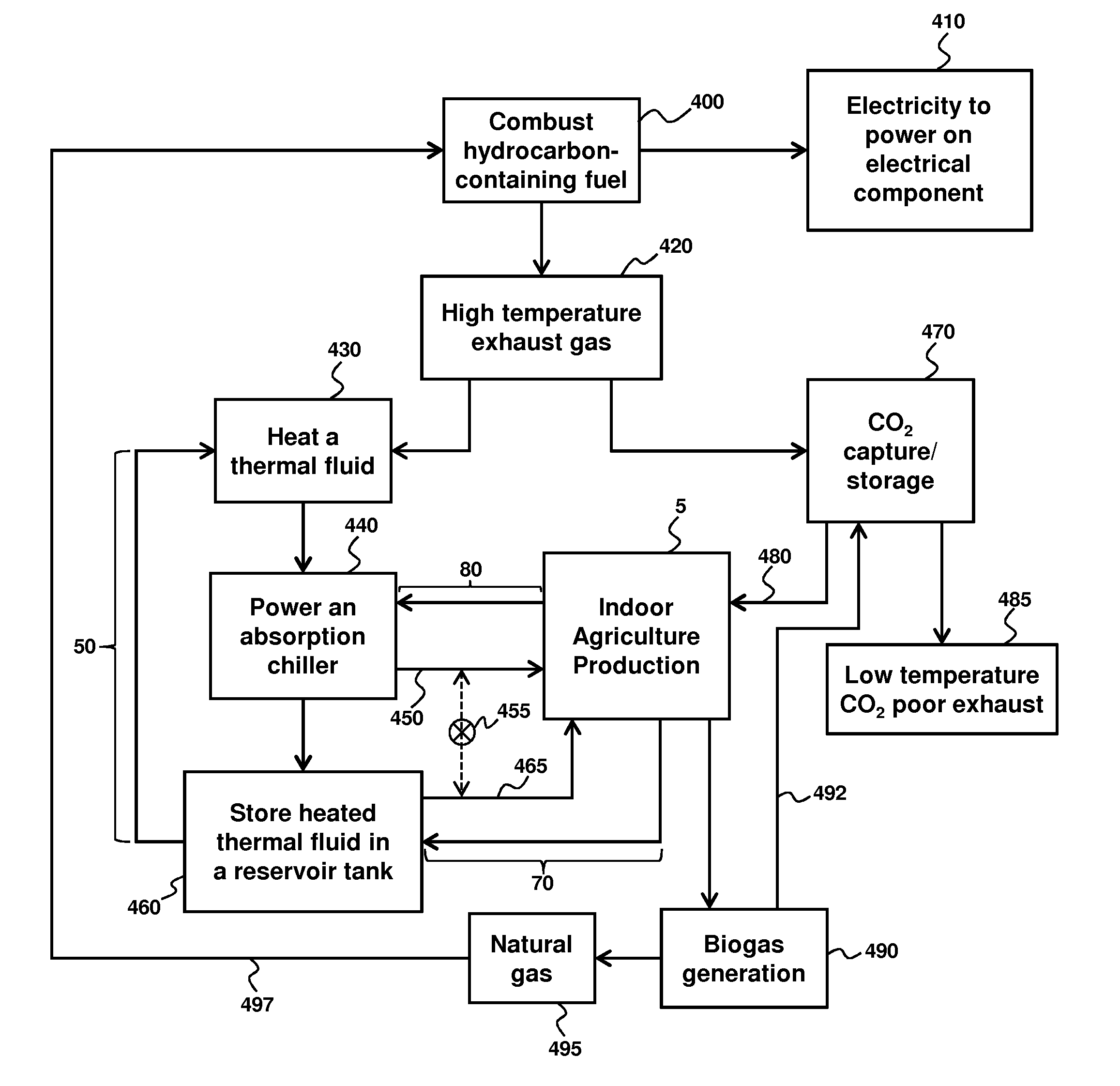
[0081]FIG. 1 is a process flow diagram summary of one method of the instant invention. A hydrocarbon-containing fuel is combusted 400 to generate electricity to power 410 one or more electrical components and to generate a high temperature exhaust gas stream 420 that is used to heat a thermal fluid 430. The electrical component may be located in the enclosed space or outside the enclosed space. The heated thermal fluid is then used to power an absorption chiller 440 which generates a cooled thermal fluid 450 which can be introduced to an enclosed space 5 such as indoor agriculture production plant in a chilled thermal fluid loop 80. The chilled thermal fluid loop then provides a return of thermal fluid from the enclosed space to the absorption chiller where the cooled thermal fluid step 450 may be repeated. In the meantime, heated thermal fluid that exits the absorption chiller may be stored in a reservoir tank 460...

example 2

Climate Control Systems

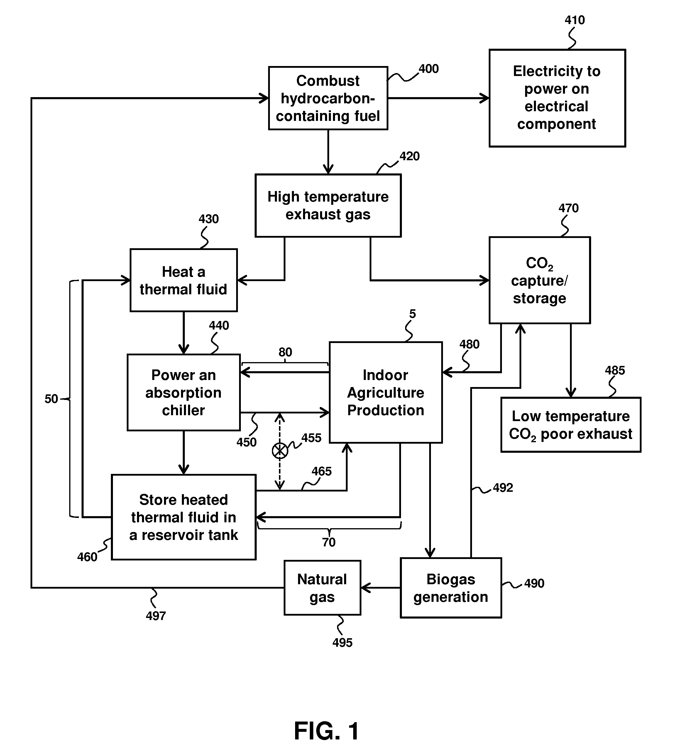
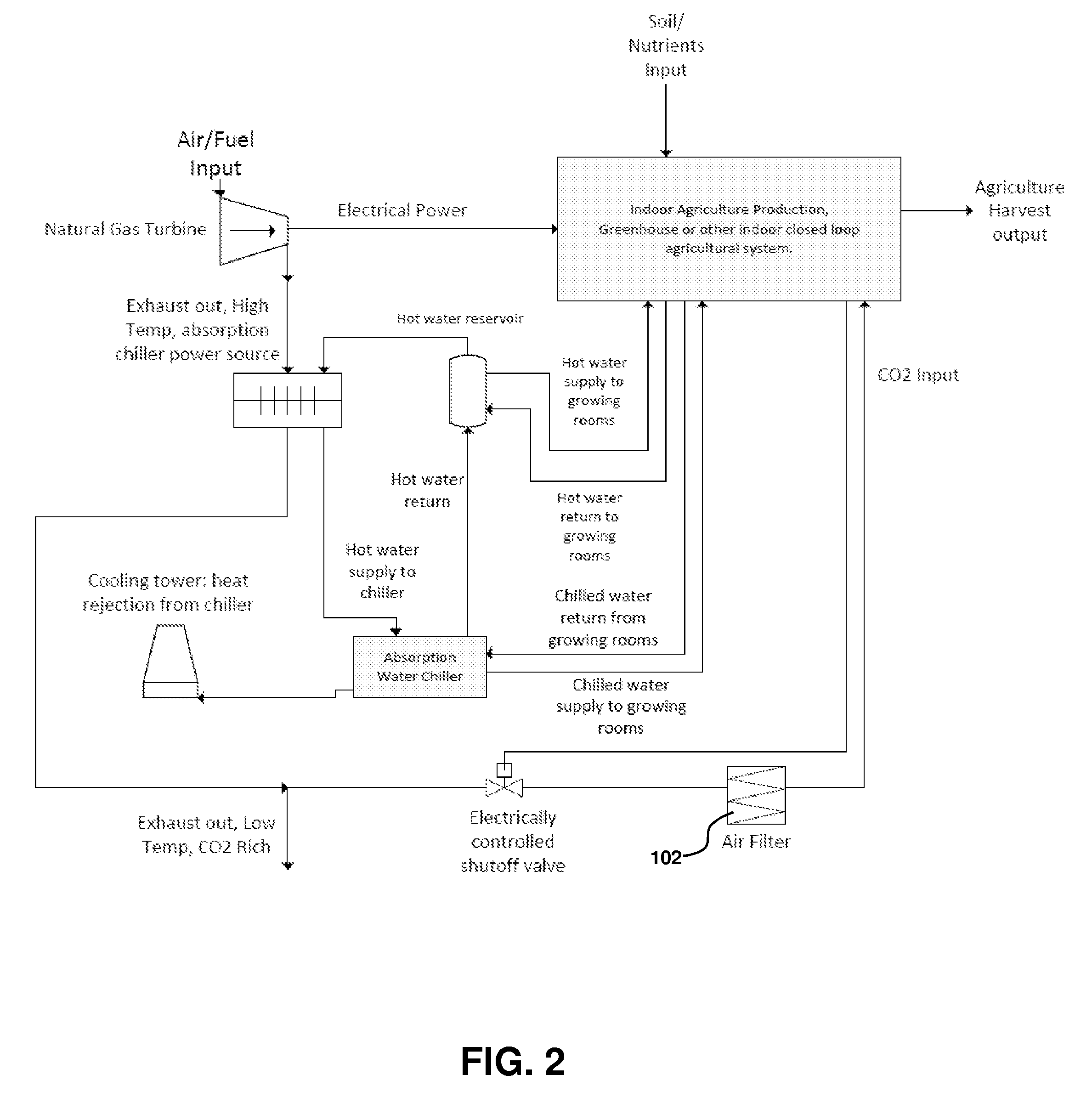
[0084]FIGS. 2-3 are schematic illustrations of two embodiments of a climate control system that provides generation and control of four aspects, specifically electricity, heat, cooling and CO2 levels. FIGS. 2 and 3 are similar with a general difference that FIG. 3 illustrates the option of biogas generation to further improve efficiency and environmental sustainability.

[0085]Enclosed space 5 is illustrated as having a number of inputs for indoor agricultural production, including soil 6 and nutrient input 7 (e.g., fertilizers and the like), as well as an agricultural harvest output 8. Other relevant inputs are the subject of the instant invention and include electrical 20, heating 76, cooling 88 and CO2 112, as explained herein below.

[0086]A hydrocarbon-fueled electrical power generator 10 provides electrical power such as by electrical power line 20. The electrical power line 20 is illustrated as connected to enclosed space 5 and may be used, for example, to ...

example 3

Absorption Chiller

[0097]Absorption chiller 60 is an energy efficient manner to obtain chilled thermal fluid in an indirect manner, wherein heated thermal fluid is used to drive chilling of a thermal fluid for subsequent cooling control. A cooling tower 62, connected to the absorption chiller via cooling tower inlet line 64 and cooling tower outlet line 66, provides additional temperature control in the absorption chiller. FIG. 4 further illustrates one example of an absorption chiller for use with the methods and systems summarized in FIGS. 1-3. Heated thermal fluid 42 from heat exchanger 40 is provided to the absorption chiller, such as in the form of steam / hot water at about 220° F.-260° F. as indicated by inlet arrow 42. The thermal fluid is then removed from the absorption chiller as indicated by outlet arrow 44, with 42 and 44 corresponding to conduits 42 and 44 of FIG. 3 and that may form part of thermal recirculating fluid loop 70. Similarly, arrows 830 and 840 refer to a chi...


PUM


Abstract

Provided are climate control systems and related methods of controlling climate in enclosed spaces. Specific applications include indoor agricultural wherein there is controlled production of electrical power along with control of heating, cooling and CO2 in the enclosed space so as maximize plant growth efficiency. The process is highly efficient and ecologically friendly with minimal energy loss and CO2 gas release to the surrounding environment.

Description

CROSS-REFERENCE TO RELATED APPLICATIONS[0001]This application claims the benefit of U.S. Provisional Patent Application No. 62 / 018,414 filed on Jun. 27, 2014, which is herein incorporated by reference in its entirety to the extent not inconsistent herewith.BACKGROUND OF INVENTION[0002]There is a need for reliable, cost-effective and cost-certain systems to control climate in an enclosed space. Provided herein are systems that facilitate control of temperature, specifically heating and cooling control, CO2 levels and electrical needs, all from a source of hydrocarbon fuel. Specific applications including rooms or buildings of an indoor agriculture facility where the climate is controlled to maximize plant growth and electrical needs are accommodated, all in a highly reliable, cost-effective, and environmentally friendly manner.[0003]An efficient form of cooling for an indoor agricultural facility is a water chilled system. Those chiller plants are all run off electricity from the ele...

Claims


Application Information

Patent Timeline
IPC IPC(8): F25B15/00F25B49/04
CPCF25B49/04F25B15/00A01G9/246Y02A40/25
Inventor JOHNSON, JORDAN
Owner SURNA
Why Eureka
Try Eureka