Intermediate case for an aircraft turbomachine made from a single casting with a lubricant duct

Active Publication Date: 2018-01-25
SN DETUDE & DE CONSTR DE MOTEURS DAVIATION S N E C M A
View PDF4 Cites 7 Cited by
  • Summary
  • Abstract
  • Description
  • Claims
  • Application Information

AI Technical Summary

Benefits of technology

The patent describes a design for an intermediate case, which simplifies the assembly of the case with an outlet guide vane. This design reduces the complexity of the lubricant duct system, which helps to reduce stress and improve the vane's performance. The design also allows for easy disassembly and maintenance of the vane. Overall, the patent provides a better solution for attaching the vane and hub of the intermediate case, improving the efficiency and performance of the heat exchanger.

Problems solved by technology

However, this environment is already highly congested by the presence of other auxiliaries, and the installation of lubricant ducts and their fluid connections to the vanes is difficult.
This problem is particularly severe when the outlet guide vanes are connected close to the flow splitter, in a narrow zone in which the space available in the hub is very limited.

Method used


Image

  • Intermediate case for an aircraft turbomachine made from a single casting with a lubricant duct
  • Intermediate case for an aircraft turbomachine made from a single casting with a lubricant duct
  • Intermediate case for an aircraft turbomachine made from a single casting with a lubricant duct

Examples


first embodiment

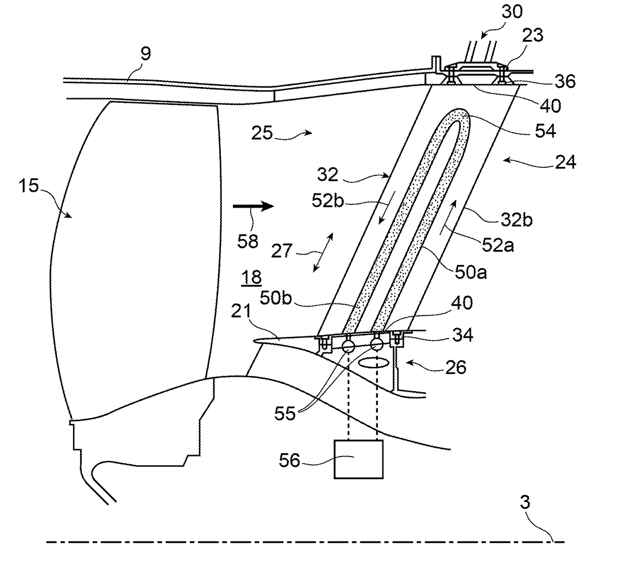
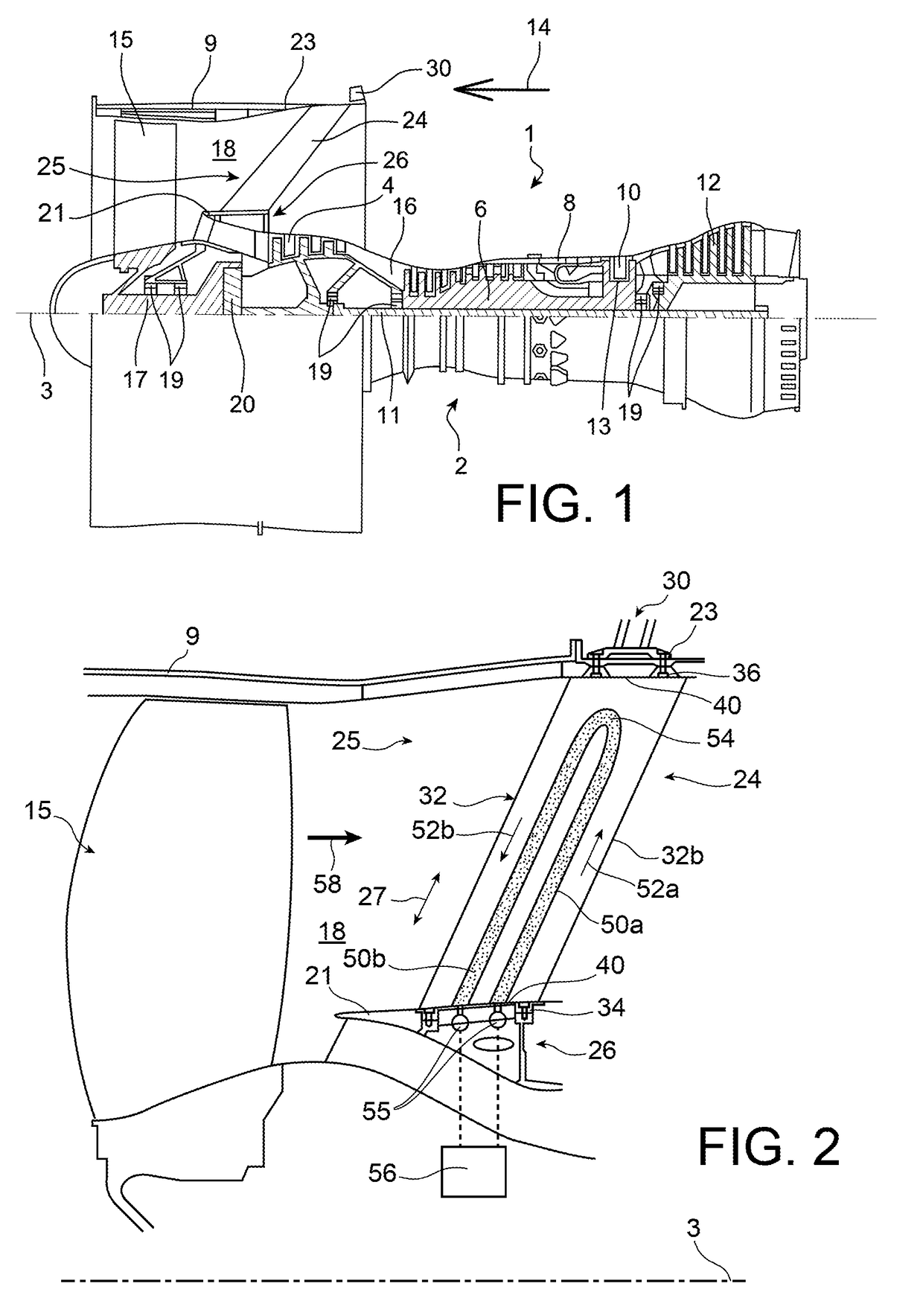
[0044]In the first embodiment shown in this FIG. 2, the aerodynamic part 32 is equipped with two inner lubricant passages 50a, 50b approximately parallel to each other and parallel to the direction of the width 25. As will be described in detail below, at least one of the vanes has two lubricant passages through which fluid circulates in opposite directions, and each passage communicates with a distinct duct. The supply-return flow of lubricant in the vane is advantageous for the passage of this lubricant in the ducts located in the hub approximately around 360 degrees, under the radially inner platforms of the fan flow, for better synergy, compactness and for easy assembly.

[0045]More precisely, a first lubricant passage 50a extends along a first main flow direction 52a of the lubricant. This direction 52a is approximately parallel to the direction of the width 25, along the direction from the root 34 towards the head 36. Similarly, there is a second lubricant passage 50b that exten...

second embodiment

[0064] shown on FIG. 6, the end pieces 88, 92 are no longer inserted in each other, but are forced into contact with each other along the direction of the central axis 98 of the opening 94. The seal 96 is then also loaded axially along this direction, by being placed flat between the two end pieces 88, 92.

[0065]According to a third embodiment shown on FIG. 7, only some of each lubricant duct 55 is made in a single casting with the intermediate case 25, and only part of each duct called the integrated part 55′ is made. In this preferred third embodiment, the integrated part 55′ extends around the entire angular sector of the duct, while remaining open radially outwards, from the axis 3. In section, it is the form of a U open in the radial direction, and closed off by a plate 55″ including the second end pieces 92 and openings 94 defined by these end pieces.

[0066]The closing plate 55″ can be attached to the integrated part 55′ by welding, by brazing, by screwed or bolted assembly, by ...


PUM


Abstract

The invention relates to an intermediate case (25) for a twin spool turbomachine for an aircraft, comprising a hub (26), an outer shell (23) and outlet guide vanes (24) installed at their ends on the hub and on the outer shell, and each of at least some of the outlet guide vanes (24) performing a heat exchanger function and comprising a lubricant passage (50a, 50b) designed to be cooled by the fan flow (58) following an outer surface of the outlet guide vane. According to the invention, the case also comprises at least one lubricant duct (55) passing along a circumferential direction of the hub (26) and at least part of which is made from a single casting with the hub, the lubricant duct (55) having at least one lateral opening communicating with the lubricant passage (50a, 50b) of at least one of the vanes (24).

Description

TECHNICAL DOMAIN[0001]This invention relates to the field of twin-spool turbomachines for aircraft, and particularly the design of the intermediate case integrating outlet guide vanes formed in the fan air stream of the turbomachine. Such “Outlet Guide Vanes” (OGV) are designed to straighten the air flow at the outlet from the fan.STATE OF PRIOR ART[0002]On some twin-spool turbomachines, it is known that outlet guide vanes can be installed at the exit from the fan to straighten the outlet flow from the fan, and possibly also to perform a structural function. This function is intended to transfer forces from the centre of the turbomachine to an outer shell located along the prolongation of the fan case. In this case, an engine attachment is conventionally formed on or close to this outer shell, to form the attachment between the turbomachine and an attachment pylon for the aircraft.[0003]It was also recently disclosed that the outlet guide vanes can be expected to perform an addition...

Claims


Application Information

Patent Timeline
IPC IPC(8): F01D9/06F02C7/16F01D25/12F01D9/04F01D25/18F01D5/18
CPCF01D9/065F01D25/18F01D5/185F01D25/12F01D9/041F01D9/042F28D2021/0089F05D2220/32F05D2240/12F05D2260/98F05D2260/205F05D2260/208F05D2260/213F02C7/16F02K3/06F02C7/18F05D2230/53F05D2230/25Y02T50/60
Inventor ZACCARDI, CEDRICJACQUEMARD, CHRISTOPHE PAULPAPIN, THIERRY GEORGES PAULPERDRIGEON, CHRISTOPHE MARCEL LUCIEN
Owner SN DETUDE & DE CONSTR DE MOTEURS DAVIATION S N E C M A
Why Eureka
Try Eureka