Pressure sensor apparatus and method

a technology of pressure sensor and pressure sensor, which is applied in the direction of fluid pressure measurement, fluid pressure measurement by electric/magnetic elements, instruments, etc., can solve the problems of tire pressure but not robust, faulty readings, and generally relatively complex devices and expensive or alternatively not particularly robus

Inactive Publication Date: 2006-08-01
HONEYWELL INT INC
View PDF13 Cites 95 Cited by
  • Summary
  • Abstract
  • Description
  • Claims
  • Application Information

AI Technical Summary

Benefits of technology

[0014]The aforementioned aspects of the invention and other objectives and advantages can now be achieved as described herein. A pressure sensor apparatus is disclosed herein, which can include a SAW sensor element, such as, for example, a SAW sensor element (e.g., a quartz sense element). The sensor element can also be implemented as another type of sensor element, such as, for example, silicon piezoresistive or ceramic capacitive sensor elements. The apparatus can also include a flexible sensor diaphragm in intimate contact with the sensor element at all pressure levels and temperatures, and a package base and a package cover for hermetically sealing the sensor element and the flexible sensor diaphragm within a hermetically sealed sensor package to provide pressure sensor data thereof.

Problems solved by technology

Such devices are generally relatively complex and expensive or alternatively are not particularly robust.
This system provides an indication of low tire pressure but is not robust.
For example mud or other debris on the wheels may cause faulty readings.
Clearly such a system simply cannot provide a reading of actual tire pressure.
However, if the tire in a rut or is parked on uneven ground, a faulty low-pressure reading is likely to be generated.
More complicated systems are capable of monitoring tire pressure.
Conventional wireless systems, however, are not durable and are expensive to design and produce.

Method used


Image

  • Pressure sensor apparatus and method
  • Pressure sensor apparatus and method
  • Pressure sensor apparatus and method

Examples


Embodiment Construction

[0028]The particular values and configurations discussed in these non-limiting examples can be varied and are cited merely to illustrate at least one embodiment of the present invention and are not intended to limit the scope of the invention.

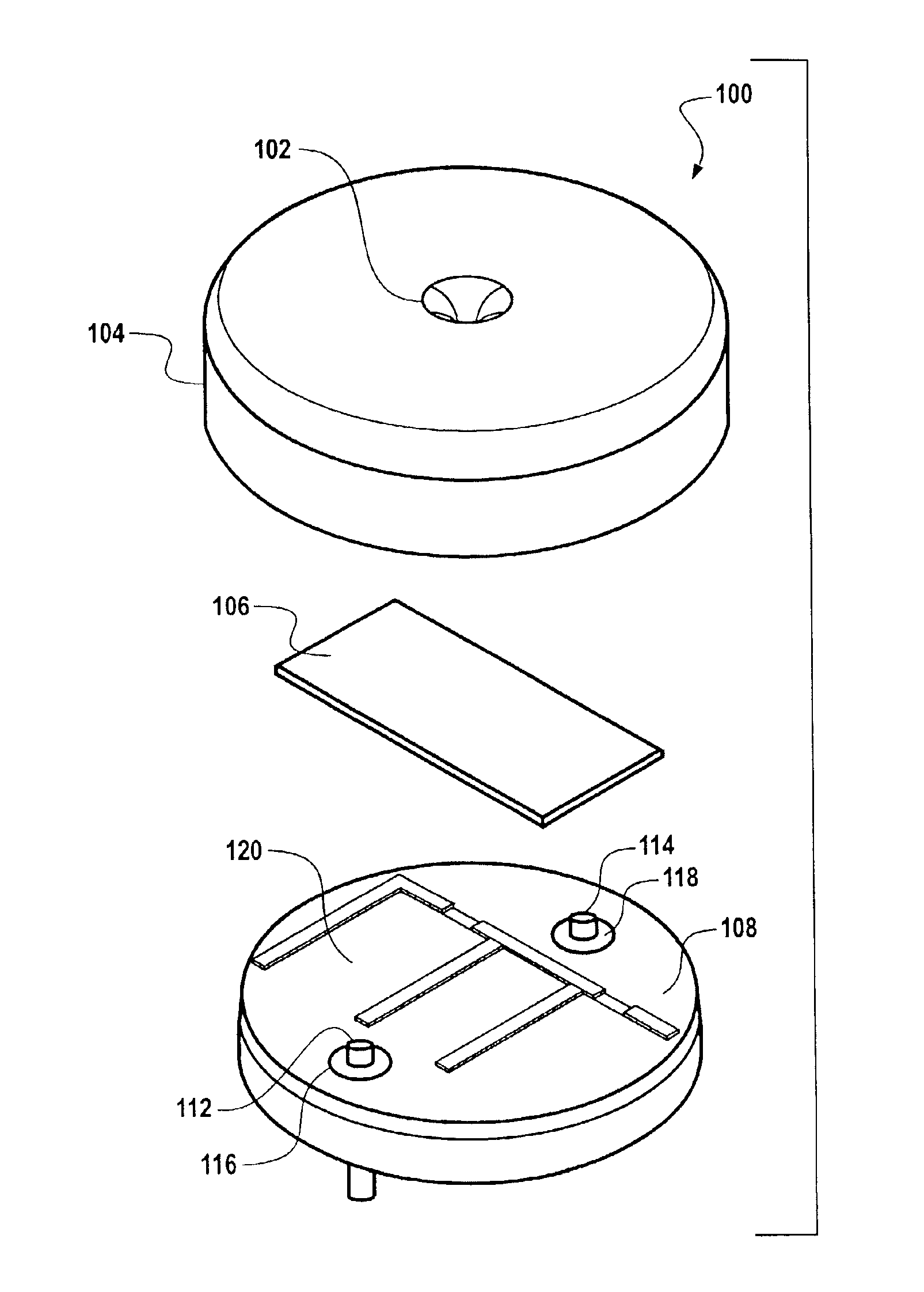
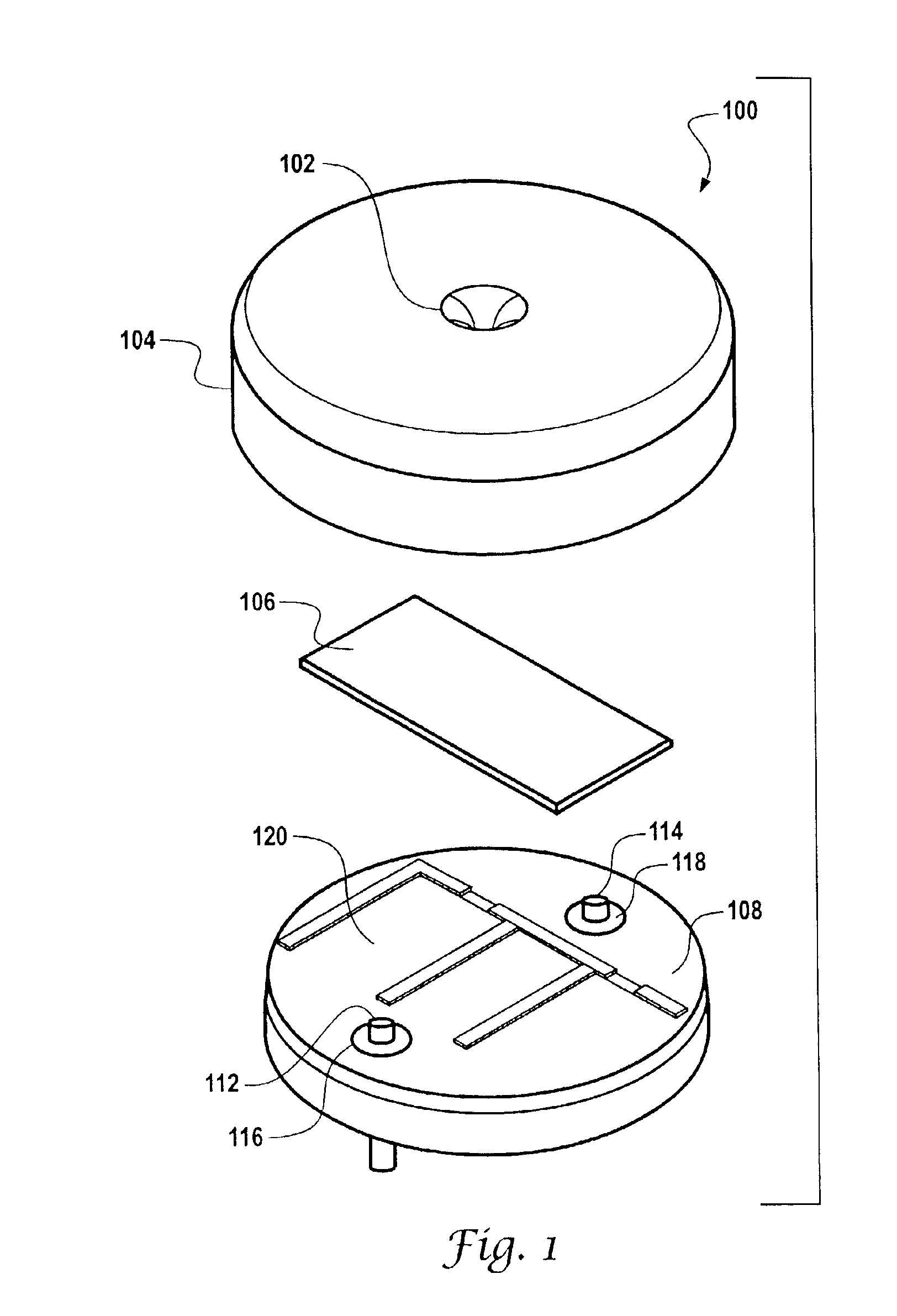
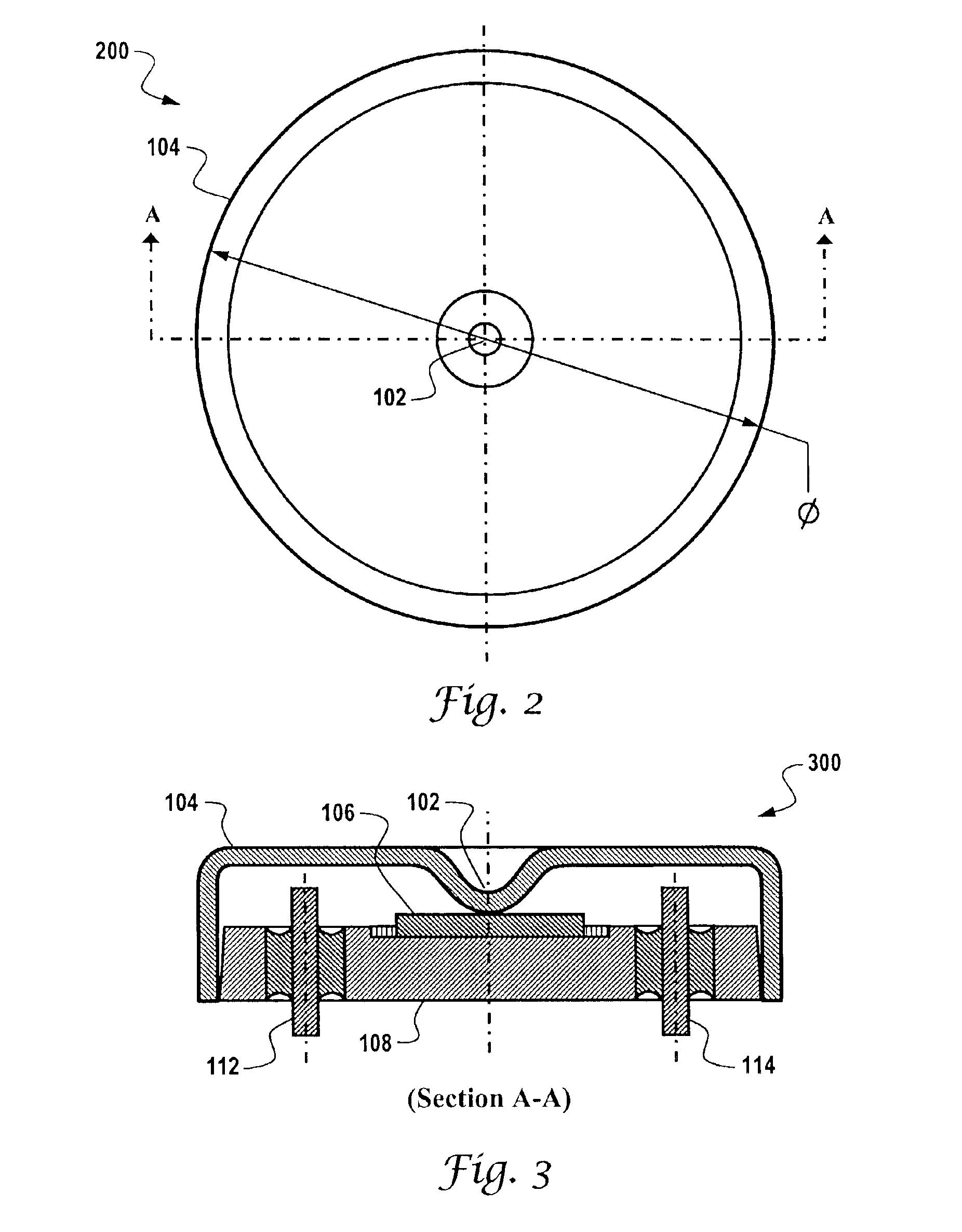
[0029]The invention described herein can be implemented, in accordance with one possible embodiment, as a product in a component in a wireless tire pressure monitoring system (TPMS). Such an embodiment can be configured as a small-size device, which is also lightweight and based on battery-less operation. The pressure sensor described herein does not consume power when implemented in the context of a TPMS operation. Thus, the present invention can be embodied in a practical and low cost design solution. Such a design can be mass-produced for automotive, heavy-duty vehicles, and commercial markets.

[0030]In accordance with one embodiment of the present invention, the pressure sensor described herein can be implemented as a SAW (surface acoustic w...


PUM

PropertyMeasurementUnit
diameteraaaaaaaaaa
diameteraaaaaaaaaa
thickaaaaaaaaaa

Abstract

A pressure sensor apparatus is disclosed herein, which generally includes a sensor element, a flexible sensor diaphragm in intimate contact with the sensor element at all pressure levels and temperatures, and a package base and a package cover for hermetically sealing the sensor element and the flexible sensor diaphragm within a hermetically sealed sensor package to provide pressure sensor data thereof. The sensor element can be implemented as a quartz sense element to produce a SAW pressures sensor. The pressure sensor apparatus can be alternatively based on other sensing technologies, such as silicon piezoresistive, ceramic capacitive and others.

Description

TECHNICAL FIELD[0001]The present invention is generally related to pressure sensing methods and systems. The present invention is additionally related to tire pressure sensors utilized in automotive, heavy-duty vehicles, and similar commercial markets. The present invention is specifically related to a wireless tire pressure monitoring system (TPMS).BACKGROUND OF THE INVENTION[0002]Various sensors are known in the pressure sensing arts. In particular, many different techniques have been proposed for sensing the pressure in tires and for delivering this information to the operator at a central location on the vehicle so that he knows that a tire is at low or high air pressure.[0003]Such pressure sensors generally communicate with the vehicle so that the sensed pressure is displayed to the operator when the vehicle is moving, i.e. the wheel rotating relative to the body of the vehicle. Such devices are generally relatively complex and expensive or alternatively are not particularly ro...

Claims


Application Information

Patent Timeline
Patent Type & Authority Patents(United States)
IPC IPC(8): H01L27/14G01L9/00
CPCG01L9/0025G01L9/0075G01L9/0052
Inventor COOK, JAMES D.GALL, KENNETH E.MALIK, KUNDAN L.MARSH, BRIAN J.
Owner HONEYWELL INT INC
Why Eureka
Try Eureka