Supercharge Your Innovation With Domain-Expert AI Agents!

Low floor drive unit assembly for an electrically driven vehicle

a technology for driving units and electric vehicles, applied in electric propulsion mounting, electric devices, transportation and packaging, etc., can solve problems such as the climb of passengers, and achieve the effects of improving packaging, improving passenger compartment utilization, and increasing passenger compartment siz

Inactive Publication Date: 2006-08-01
MERITOR HEAVY VEHICLE SYST
View PDF47 Cites 21 Cited by
  • Summary
  • Abstract
  • Description
  • Claims
  • Application Information

AI Technical Summary

Benefits of technology

This configuration lowers the interior floor, enhances passenger space, and provides flexible packaging for other vehicle components, improving handicapped access and reducing the overall vehicle height.

Problems solved by technology

It is undesirable, however, to have passengers climb steps to reach the aisle and seating areas.

Method used


Image

  • Low floor drive unit assembly for an electrically driven vehicle
  • Low floor drive unit assembly for an electrically driven vehicle
  • Low floor drive unit assembly for an electrically driven vehicle

Examples


Embodiment Construction

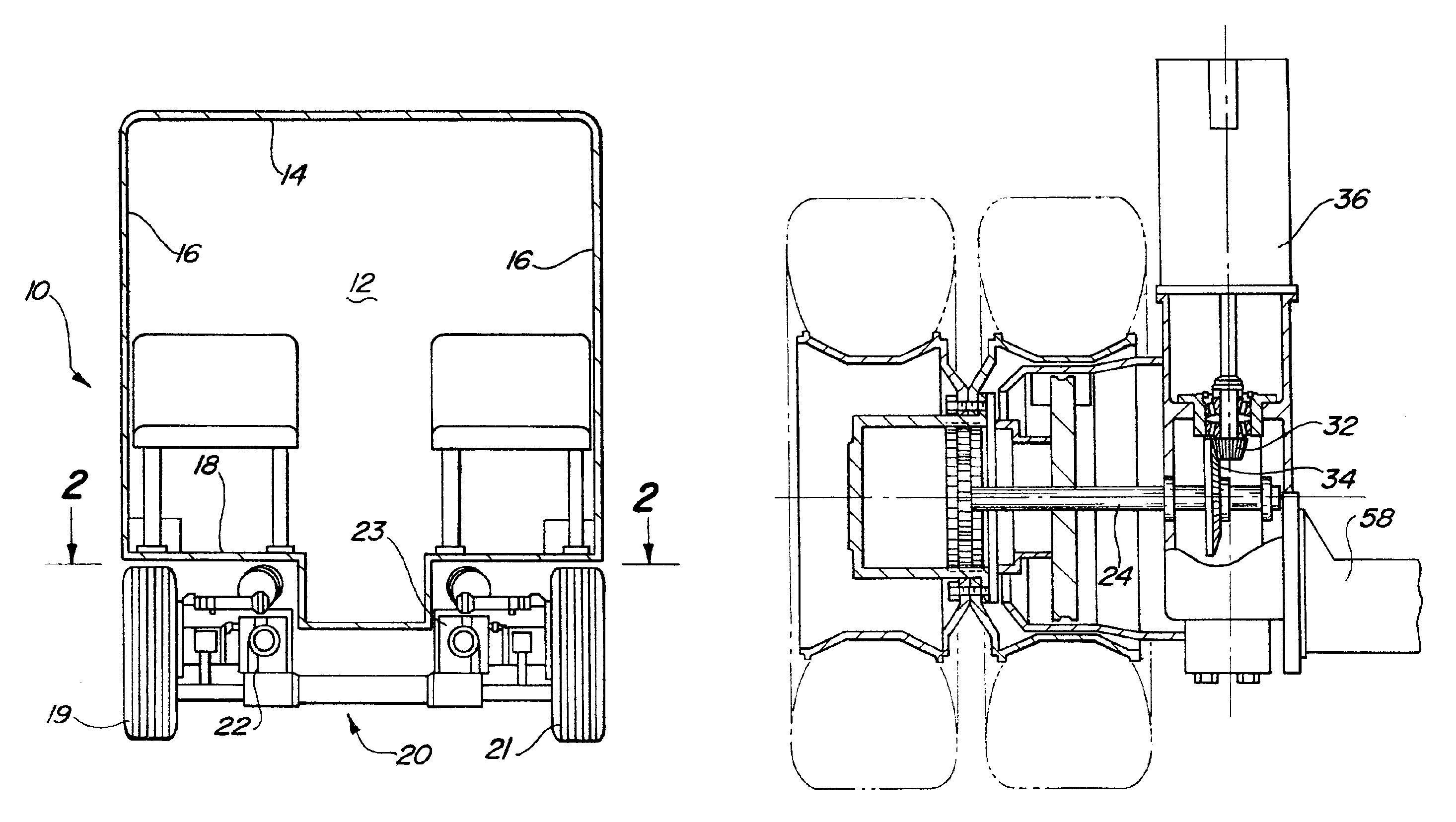
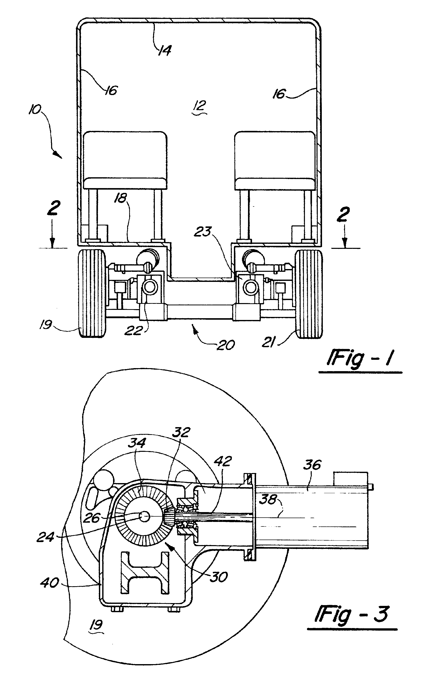
[0018]Referring to the Figures, wherein like numerals indicate like or corresponding parts throughout the several views, an automotive vehicle is shown generally at 10. As shown in FIG. 1, automotive vehicle 10 includes a passenger compartment 12 defined by a roof 14, two side walls 16, and a vehicle floor 18. A pair of wheels 19,21 are driven by an automotive vehicle drive unit assembly, generally shown at 20, which has a first unit 22 and a second unit 23. It should be understood that vehicle 10 is typically provided with a pair of drive units and several pairs of wheels.

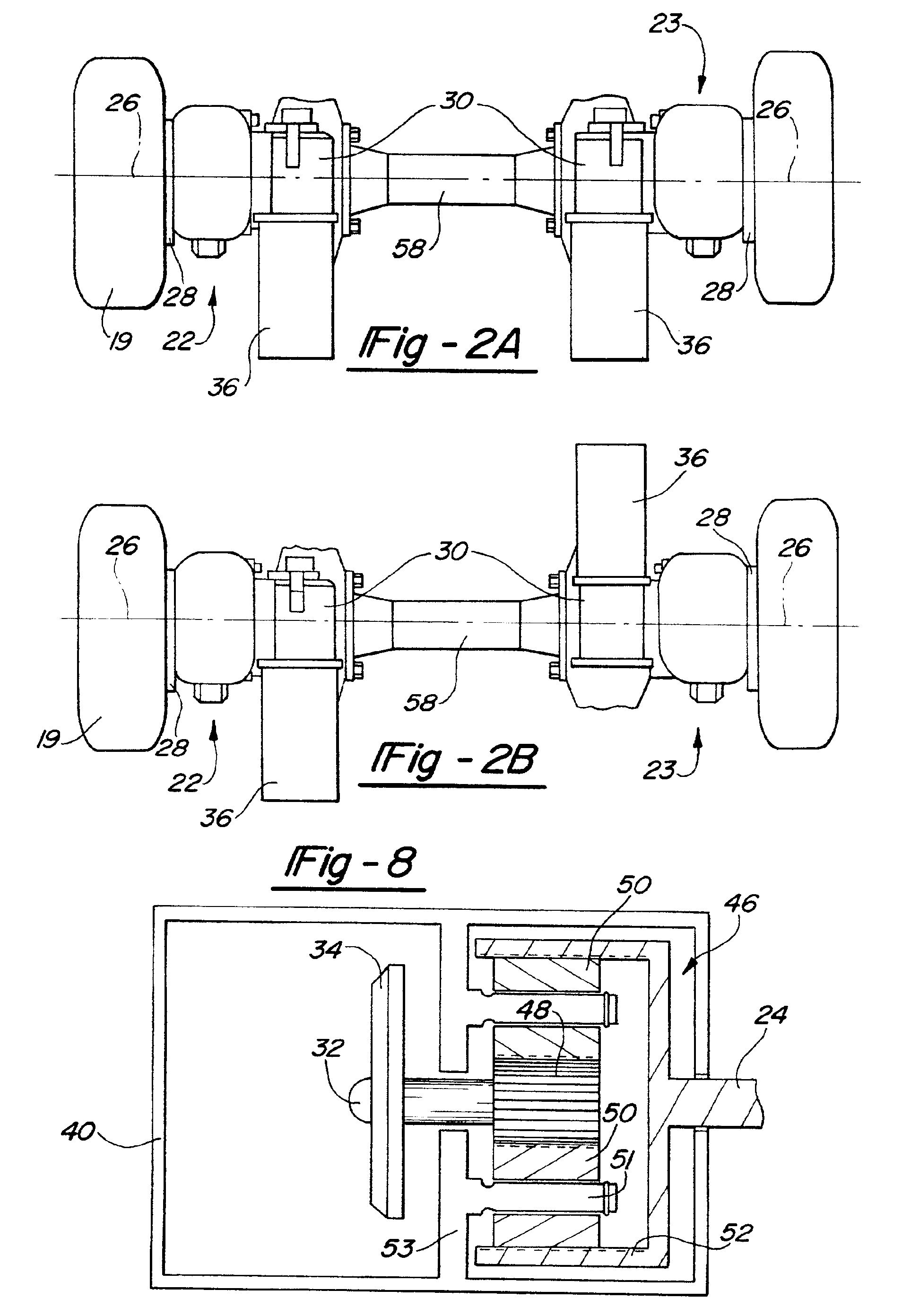
[0019]As shown in FIG. 2A, the first unit and second units 22 and 23 define an axis of rotation 26. As shown in FIG. 3, a first driving axle shaft 24 drives a first wheel hub 28 which revolves about the axis 26 of the first driving axle shaft 24.

[0020]A first gear set 30, located adjacent to the first wheel 19, is comprised of a pinion gear 32 and a ring gear 34 which together drive the first wheel hub 28. A first...


PUM


Abstract

An automotive vehicle drive unit assembly which is located near the sides of a vehicle includes a first driving axle shaft, a second driving axle shaft, a first gear box, a second gear box, a first electric motor, and a second electric motor. The first driving axle shaft drives a first wheel hub of the vehicle and the second driving axle shaft drives a second wheel hub. Together the first and second driving axle shafts define an axis of rotation about which the first and second wheel hubs rotate. The first gear set drives the first wheel and the second gear set drives the second wheel. A first electric motor is mounted in an angular relationship relative to the axis of rotation and drives the first gear set. A second electric motor is mounted in an angular relationship relative to the axis of rotation and drives the second gear set. A plurality of electric motors can be used to drive each wheel hub.

Description

[0001]This application is a continuation of Ser. No. 08 / 801,531 file on Feb. 18, 1997.BACKGROUND OF THE INVENTION[0002]This invention relates to a unique drive arrangement for electrically driving the wheels of a vehicle in such a way that the floor of the vehicle may be lower than was the case in the prior art.[0003]Mass transit vehicles, such as a bus or trolley car, typically have seats aligned at the lateral sides of the vehicle, with a central aisle extending along the vehicle. The seats are typically at a higher vertical location than the aisle, and thus cover the wheels. It would be desirable to have the aisle positioned relatively low to the ground. This would provide increased passenger space within the body of the vehicle, and may allow the designer to reduce the overall height of the mass transit vehicle. Other advantages to having a lower floor position include improved handicapped access and greater ease in the loading and unloading of passengers.[0004]Mass transit vehi...

Claims


Application Information

Patent Timeline
Patent Type & Authority Patents(United States)
IPC IPC(8): B60K1/02B60K7/00B60K17/04B60K17/22
CPCB60K1/02B60K7/0007B60K17/046B60K17/22B60K17/043B60Y2200/1432B60K2007/0038B60K2007/0069B60K2007/0076B60K2007/0084B60L2220/46B60K2007/003B60L15/007B60L2200/18B60L2220/42B60L2220/50Y02T10/64
Inventor RUPPERT, MALCOLM F.BRILL, LAWRENCE DOYLESULLIVAN, WILLIAM CARLSWANSON, GLEN E.
Owner MERITOR HEAVY VEHICLE SYST
Features
  • R&D
  • Intellectual Property
  • Life Sciences
  • Materials
  • Tech Scout
  • Unparalleled Data Quality
  • Higher Quality Content
  • 60% Fewer Hallucinations
Learn More