Method and device for detecting the speed of a pump

a technology of pump motor and speed detection, which is applied in the direction of positive displacement liquid engine, pump parameter, instrument, etc., can solve the problem that the known method of detecting the speed of motors, particularly pump motors, tends to be relatively expensiv

Inactive Publication Date: 2006-08-01
ROBERT BOSCH GMBH
View PDF7 Cites 19 Cited by
  • Summary
  • Abstract
  • Description
  • Claims
  • Application Information

AI Technical Summary

Benefits of technology

[0006]The detection method according to the present invention requires no correction to compensate for the temperature factor, and the method is substantially robust with respect to disturbing reflections between a pump and a reservoir acted upon by the pump.
[0007]In accordance with the present invention, it is advantageous to filter out high-frequency interferences in the pressure signal caused by the driven pump, using suitable filtering means. Similarly, it is advantageous to filter out low-frequency interferences in the pressure signal, particularly a DC voltage component, which stems from the rising pressure in the reservoir acted upon by the pump. A pressure signal that has been filtered of high-frequency and / or low-frequency interferences, may be further processed in a simple manner.
[0009]To implement the filters mentioned, suitable filtering means, e.g., a low-pass filter or a high-pass filter, may be used. Such filters may be made available inexpensively.

Problems solved by technology

In general, known methods for detecting the speed of motors, particularly pump motors, tend to be relatively costly.

Method used


Image

  • Method and device for detecting the speed of a pump
  • Method and device for detecting the speed of a pump
  • Method and device for detecting the speed of a pump

Examples


Embodiment Construction

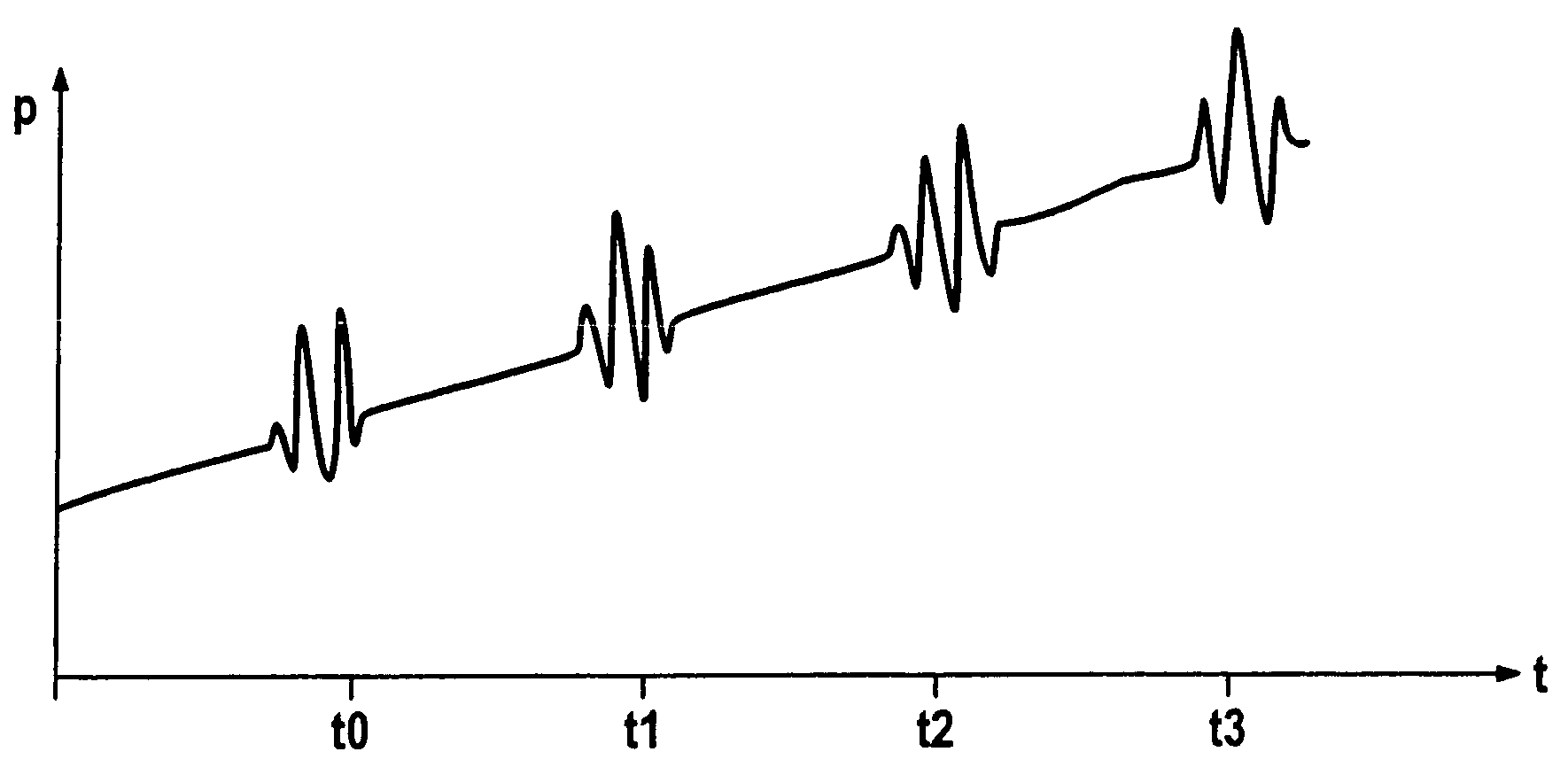
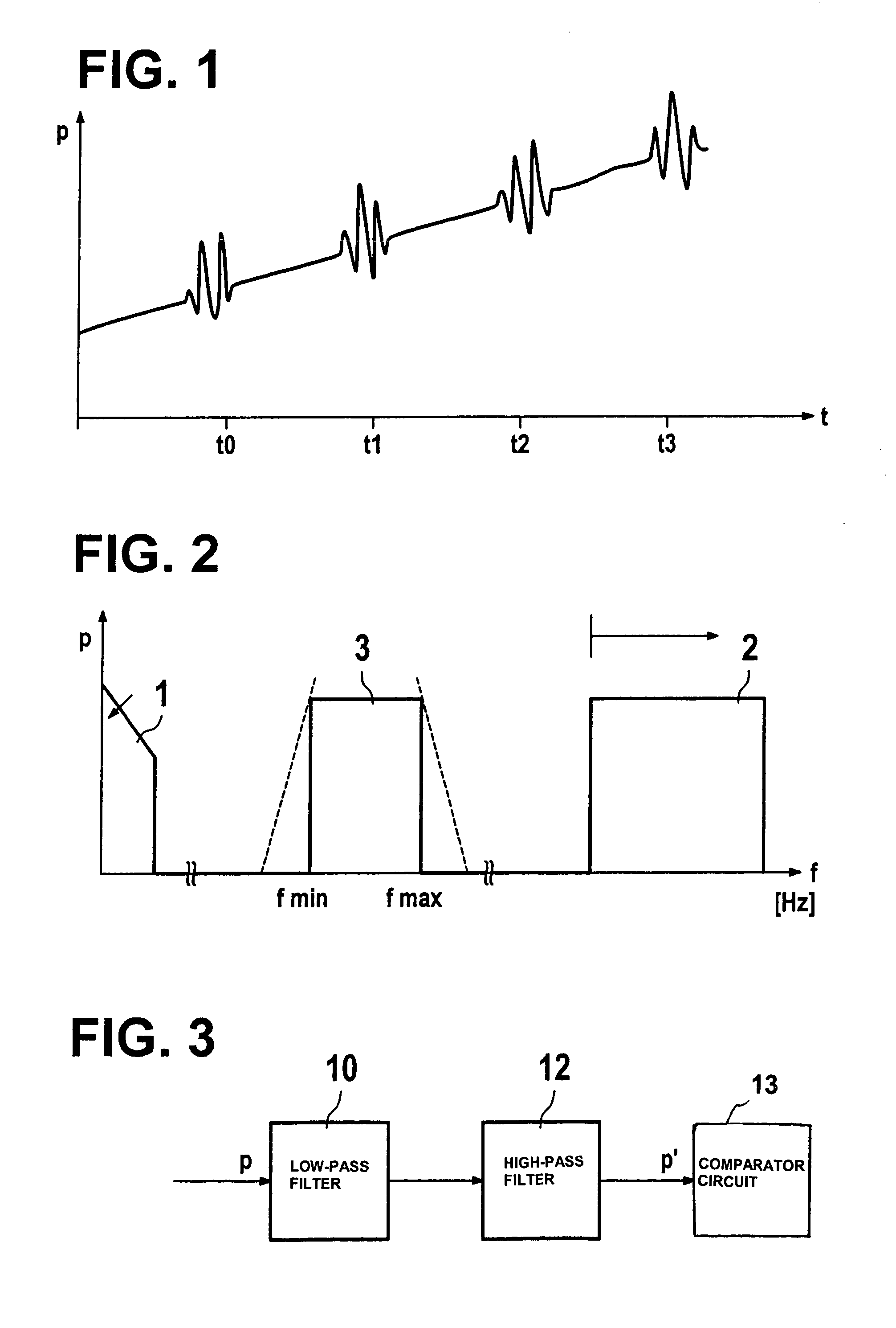
[0016]In a hydraulic pump system, a pump is driven by a pump motor to deliver a hydraulic fluid, via a pressure-media line, into a high-pressure reservoir. During this delivery, pressure peaks develop within the framework of a pressure signal in the pressure-media line and / or in the high-pressure reservoir, the time interval between the pressure peaks being a measure of the speed of the pump motor. The pressure signal is detected by a suitable sensor and converted into a corresponding current signal or voltage signal. A signal of this type, after an optional digitalization, is further processed in a computing device.

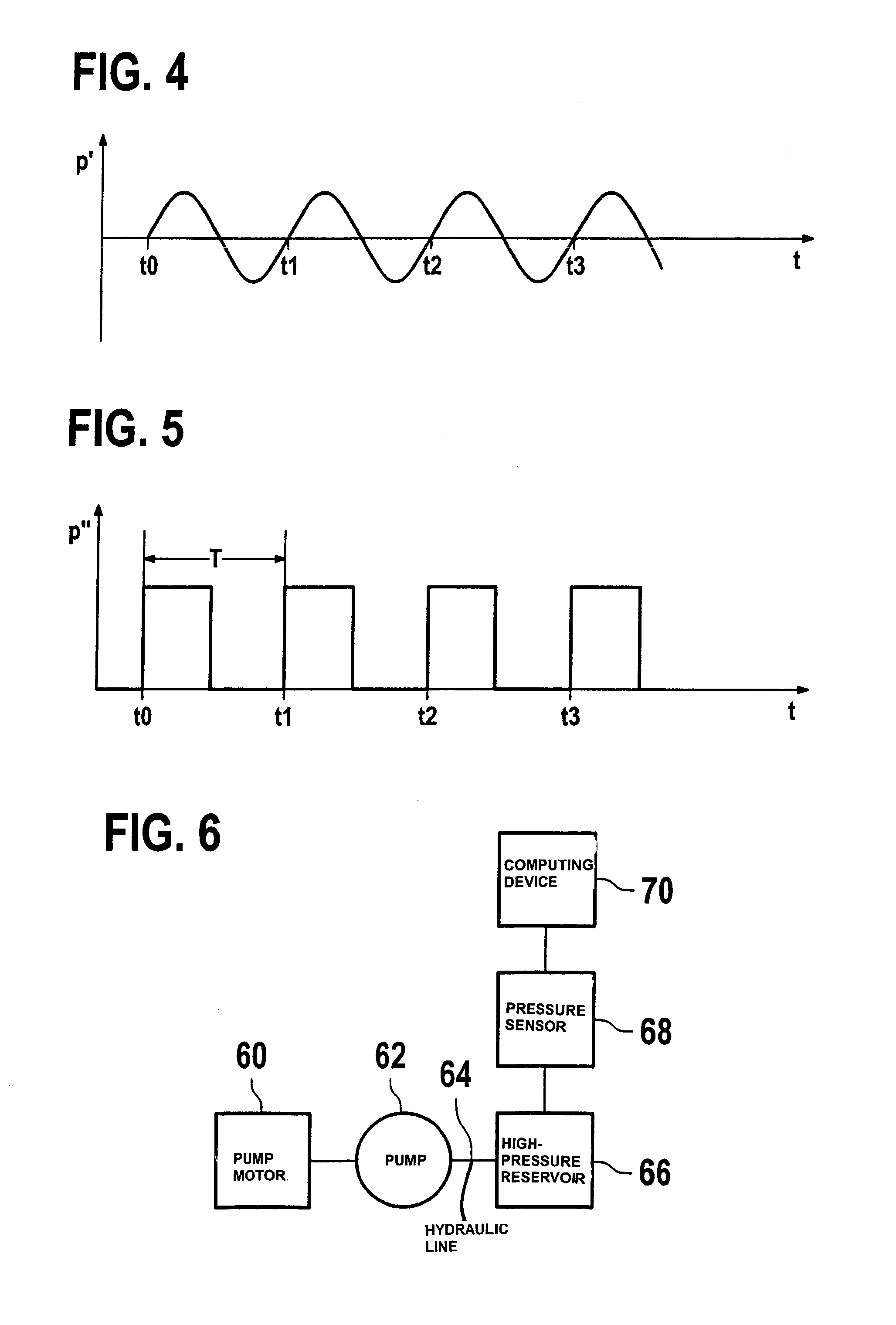
[0017]A schematic representation of a hydraulic pump system in accordance with the present invention is shown in FIG. 6. Here, 60 designates a pump motor which drives a pump 62. Pump 62 in turn delivers hydraulic fluid via a hydraulic line 64 into a high-pressure reservoir 66. The pressure created in this high-pressure reservoir is detected by a pressure sensor 68 to obt...


PUM


Abstract

A method and a system for detecting the speed of a pump motor of a hydraulic pump system are provided, in which pump system a pump is driven by a pump motor to deliver hydraulic fluid into a pump reservoir. In accordance with the present invention, a pressure signal representing the fluid-delivery activity of the pump is detected, and the pressure peaks within this pressure signal identified. The speed of the pump motor is determined on the basis of the frequency or the time intervals of these pressure peaks.

Description

FIELD OF THE INVENTION[0001]The present invention relates to a method and a system for detecting the speed of a pump motor.BACKGROUND INFORMATION[0002]It is known in the art to determine the speed of a pump motor using dedicated speed sensors. Given a clocked operation of a pump motor, the speed of the pump motor may also be ascertained, in the undriven phase, on the basis of the generating voltage of the pump motor. Such methods are used in the regulation of the pump motor within the framework of an electrohydraulic braking system, for example.[0003]German Patent 41 33 269 describes a method for measuring the speed of a rotating part surrounded by a housing, in which a further signal that is a function of the speed is detected, and this further signal is filtered and digitalized, as well as Fourier-transformed twice. The speed is ascertained from the spectrum thus obtained, by evaluating the absolute maximum. A relatively great computing power is necessary to implement such a speed...

Claims


Application Information

Patent Timeline
IPC IPC(8): F04B49/06F04B51/00G01P3/481F04C14/08G01P3/26G01P3/28G01P3/48G01P3/489
CPCB60T8/4059F04B51/00G01P3/489G01P3/26G01P3/28G01P3/48F04C14/08F04B2201/1201F04B2203/0209F04B2205/05F04C2270/18F04C2270/80
Inventor SIEVERT, HOLGERHACHTEL, JUERGENHERTLEIN, GUENTHER
Owner ROBERT BOSCH GMBH
Why Eureka
Try Eureka