Axle drive block with a differential lock

a technology of differential lock and drive block, which is applied in the direction of differential gearing, belt/chain/gearing, toothed gearing, etc., can solve the problems of not being suitable for interaction with brake force and slip-limiting system (abs, esp), not only complicated and bulky, and unfavorable wear behavior, so as to achieve the effect of less space required and less manufacturing expenditur

Inactive Publication Date: 2006-08-01
MAGNA STEYR FAHRZEUGTECHN
View PDF14 Cites 15 Cited by
  • Summary
  • Abstract
  • Description
  • Claims
  • Application Information

AI Technical Summary

Benefits of technology

[0011]In another possible embodiment, the second planet carrier and / or the ring has a planar end surface with depressions which form ramps and accommodate rolling bodies. The action therefore occurs virtually without any friction and in a more sensitive manner. In addition, the space required and the outlay on manufacturing are thus smaller.

Problems solved by technology

The latter is not only complicated and bulky (for which reason it has to be driven via a hollow shaft and arranged outside the housing of the two differentials), it also has the disadvantage of not being suitable for interaction with brake-force and slip-limiting systems (ABS, ESP).
In particular, with only a partial locking by means of friction, an asymmetrical distribution of torque with respect to the longitudinal axis of the vehicle would be produced, which is not allowed.
A lock of this type is specified, for example, also in a torsen differential of particular design, but has an unfavorable behavior in terms of wear.

Method used


Image

  • Axle drive block with a differential lock
  • Axle drive block with a differential lock
  • Axle drive block with a differential lock

Examples


Embodiment Construction

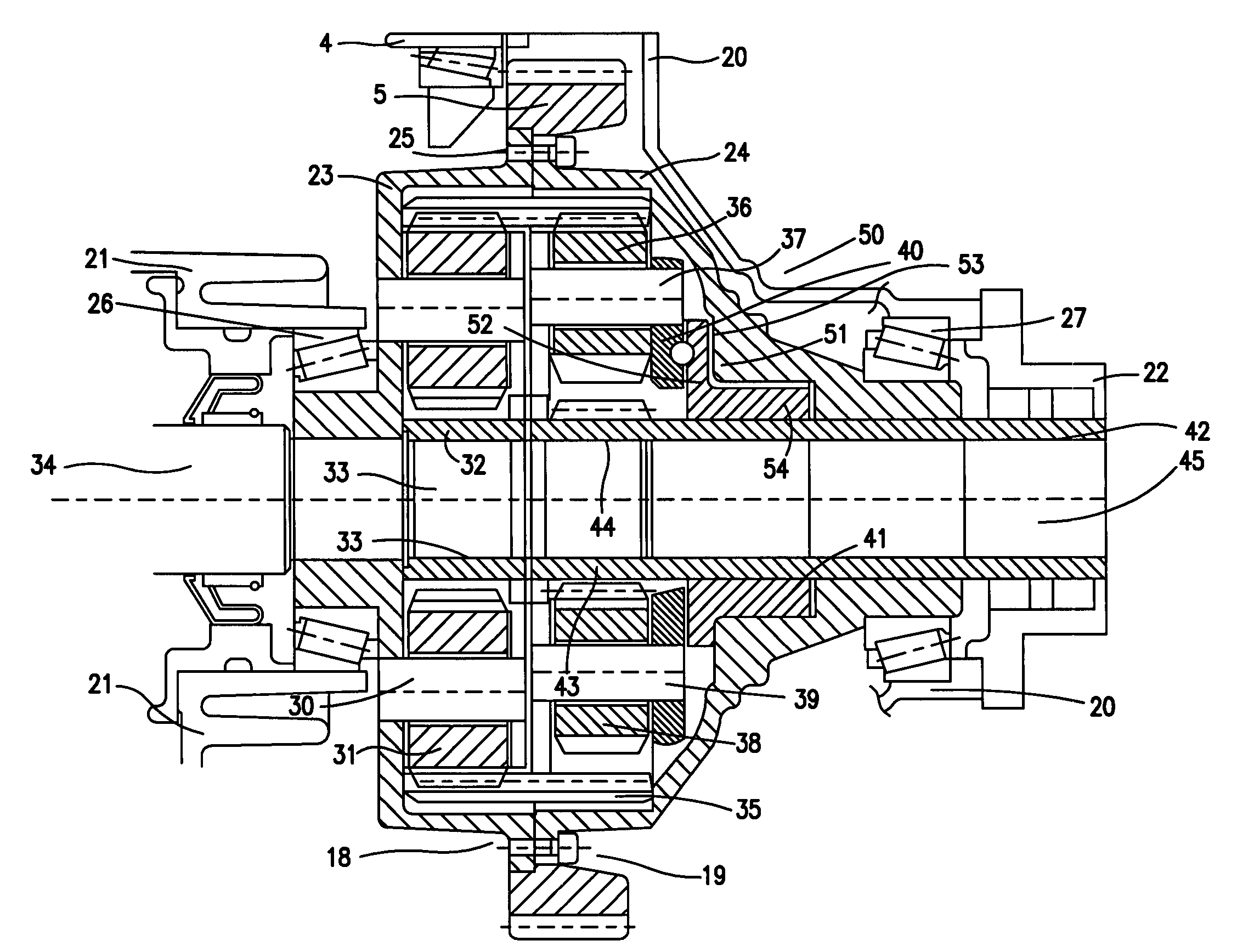
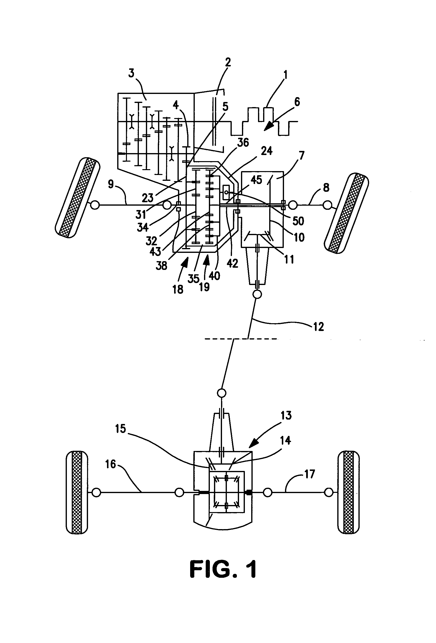
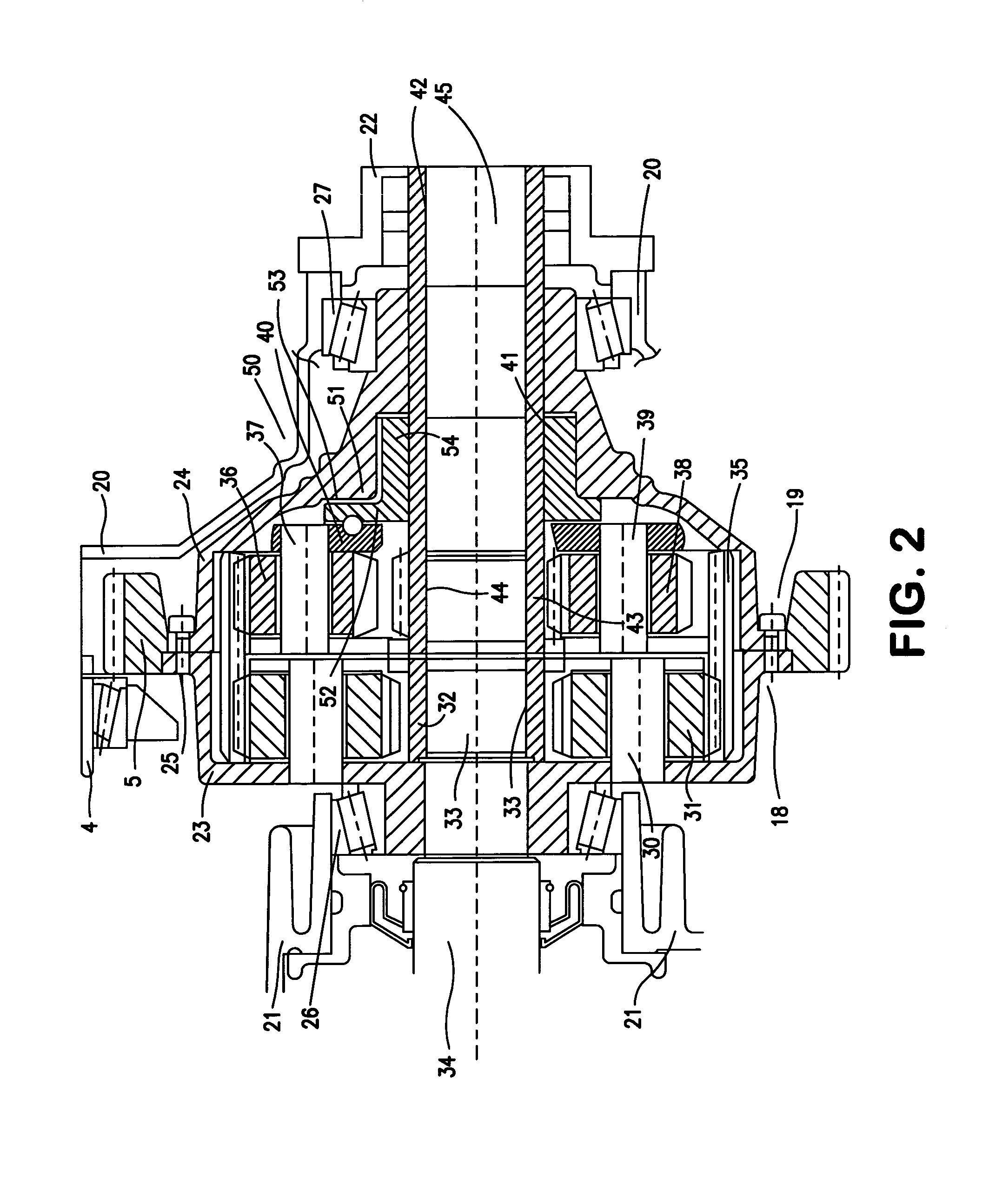
[0021]In the all-wheel-drive motor vehicle illustrated in FIG. 1, the engine is referred to by 1, the clutch by 2, and the manual transmission by 3. The transmission 3 ends in a driven gearwheel 4 which meshes with a large driving gearwheel 5. The driving gearwheel 5 is already part of the axle-drive block 6. The latter is adjoined by a power take-off 7 for the rear axle drive and by a right and a left half axle 8, 9 for the drive of the front wheels. Located in the interior of the power take-off 7 is a pair of bevel gears 10, 11, and the torque for the rear axle is fed via a propeller shaft 12 to a, for example, conventional differential transmission 13, in which the half axles 16, 17 of the rear wheels are driven in a known manner via a pair of bevel gears 14, 15. A first and a second planetary gear 18, 19 are located in the interior of the axle-drive block 6 and will be described in greater detail below.

[0022]The rotating part of the axle-drive block illustrated in FIG. 2 is, sta...


PUM


Abstract

An axle drive block for a motor vehicle, comprising a first and a second differential in a driven housing. Both of the differentials are coaxially aligned planetary spur gears, the sun wheels of which are drivably connected to the semiaxes of the first driven axle. The planet wheels of both differentials mesh the joint ring gear of the sun wheels. In order to lock the interaxle differential, the housing is provided with a first striking surface interacting with a second striking surface which is pressed thereto by ball ramps.

Description

BACKGROUND OF THE INVENTION[0001]The invention involves an axle-drive block for motor vehicles having a first and a second driven axle which contains a first and a second differential in a housing driven by an engine / transmission block, the first differential distributing the torque fed to it between a first half axle of the first driven axle and the second differential, and the second differential further distributing the torque fed to it between a second half axle of the first driven axle and a power take-off for the second driven axle, the two differentials being spur-gear-type planetary gears with parallel axes, the sun wheels of which are in each case connected in terms of drive to the half axles of the first driven axle, and planet wheels of the two differentials meshing with the common ring gear of said planetary gears, one planet carrier being connected in a rotationally fixed manner to the housing accommodating the two differentials and the other planet carrier being connec...

Claims


Application Information

Patent Timeline
Patent Type & Authority Patents(United States)
IPC IPC(8): F16H48/06B60K17/346B60K23/08F16H48/22
CPCB60K23/0808B60K17/3465
Inventor PECNIK, HERMANNSTELZL, HELMUT
Owner MAGNA STEYR FAHRZEUGTECHN
Why Eureka
Try Eureka