Method for tracking motion phase of an object for correcting organ motion artifacts in X-ray CT systems

a technology of ct system and motion phase, applied in the field of medical imaging, can solve problems such as blurring of motion artifacts, impede diagnosis, erroneous diagnosis, etc., and achieve the effects of improving image quality, removing motion artifacts successfully, and high benefit in cardiac imaging

Inactive Publication Date: 2006-08-01
CANAMET CANADIAN NAT MEDICAL TECH
View PDF7 Cites 67 Cited by
  • Summary
  • Abstract
  • Description
  • Claims
  • Application Information

AI Technical Summary

Benefits of technology

[0006]It is further an object of the invention to substantially improve image quality of tomographic images by substantially removing motion artifacts.
[0039]Reconstructed tomographical images clearly show a substantial improvement in image quality by successfully removing motion artifacts using the method for tracking motion phase of an object according to the invention. Employment of the method for tracking motion phase of an object according to the invention is highly beneficial in cardiac imaging using X-ray CT scan. The method is easily implemented as retrofit into existing X-ray CT scanners including helical X-ray CT scanners, for example, as executable commands provided on a storage medium for execution on an existing signal processing system.

Problems solved by technology

The violation of this assumption causes motion artifacts, which appear as blurring, doubling and / or streaking in the reconstructed image.
As is evident, such artifacts substantially impede diagnosis or even lead to erroneous diagnosis.
However, the organ motion is much more complex and these techniques have a severely limited ability for correcting organ motion.
Although the correction methods disclosed in the above cited references reduce the adverse effects of motion to some extent, none of these methods substantially removes the motion artifacts from the reconstructed tomographic images.

Method used


Image

  • Method for tracking motion phase of an object for correcting organ motion artifacts in X-ray CT systems
  • Method for tracking motion phase of an object for correcting organ motion artifacts in X-ray CT systems
  • Method for tracking motion phase of an object for correcting organ motion artifacts in X-ray CT systems

Examples


first embodiment

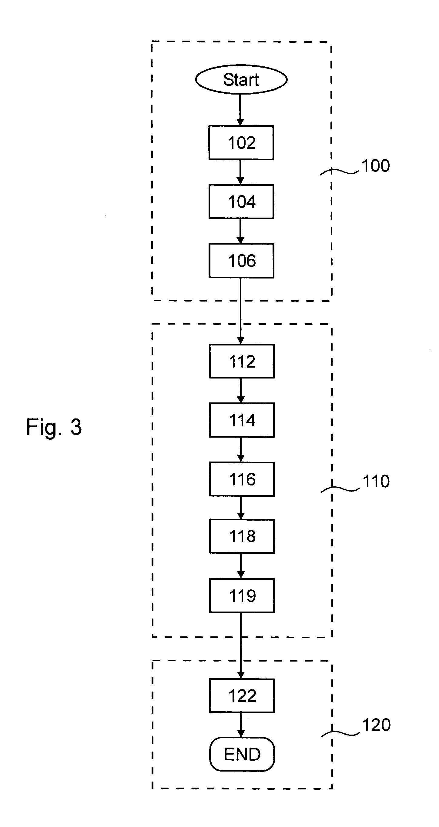
[0078]In the following, two embodiments of the method for tracking motion phase of an object according to the invention, as indicated above in boxes 114 to 118, will now be described in more detail. In the first embodiment a Spatial Overlap Correlator (SOC) is combined with an unwrapping filter for tracking the cardiac motion and accurately detecting the less active phase therefrom. The SOC concept has been described in detail by the present inventor in Stergiopoulos, S.: “Otpimum Bearing Resolution for a Moving Towed Array and Extension of its Physical Aperture”, JASA, 87(5), pp. 2128–2140, 1990, and in Stergiopoulos, S.: “Implementation of Adaptive and Synthetic Aperture Processing in Real-Time Sonar Systems”, Proc IEEE, 86(2), pp. 358–396, 1998. The process of SOC is best understood by a simple example. Consider two photographs taken at time instances t0 and t0+Δt of a field of view including a moving train and stationary objects such as trees and houses. If corresponding pixels ...

second embodiment

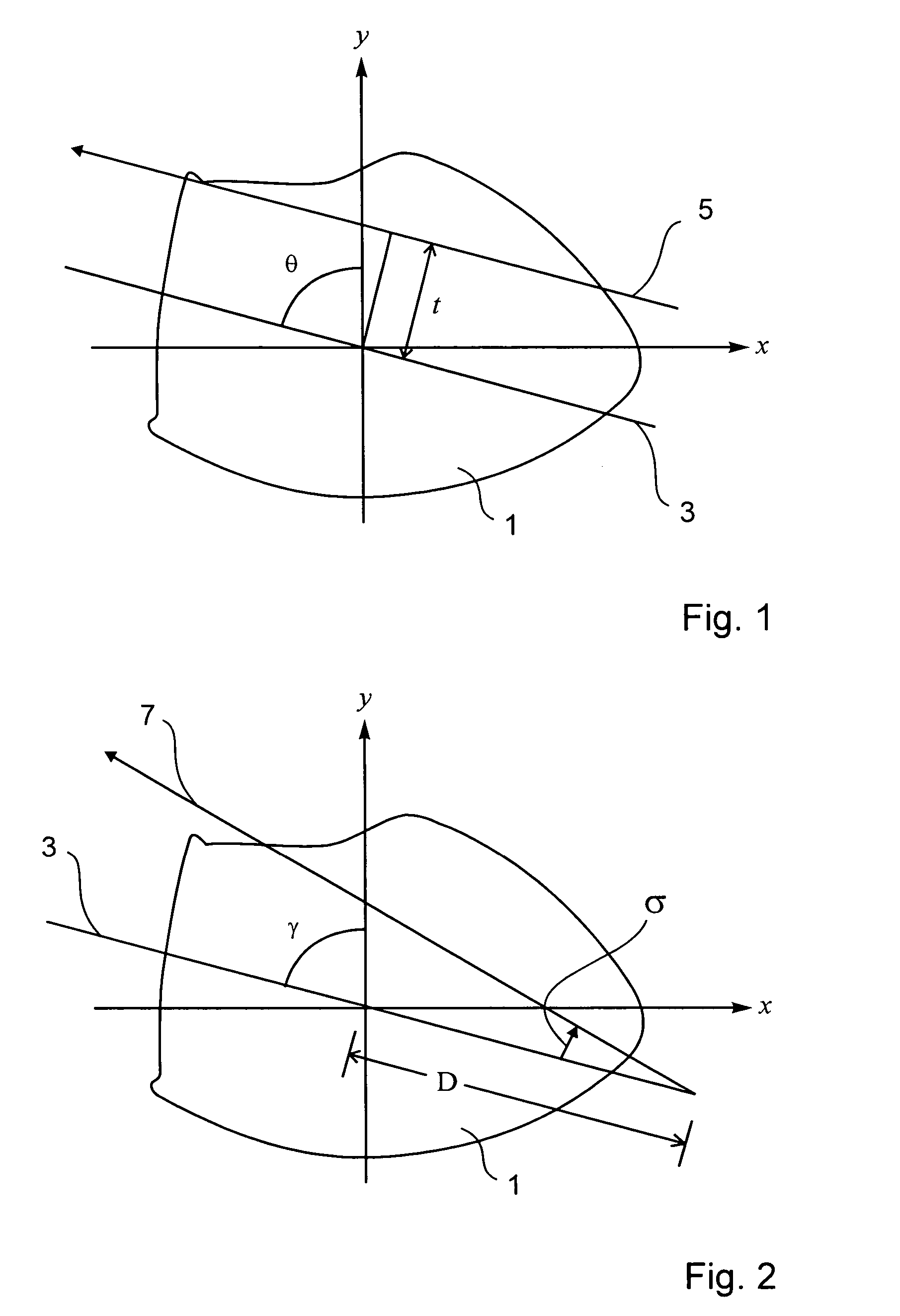
[0091]In the following, the method for tracking motion phase of an object according to the invention will be described. Here, the less active phase of the cardiac cycle is identified using a property of the Radon transform. The property will be briefly described before its application for tracking the motion phase of an object is explained.

[0092]Let P(θ, t) be the Radon transform of an object f(x, y) contained within a unit circle, which is possible without loss of generality. The integral

[0093]∫-11⁢P⁡(θ,t)⁢tk⁢⁢ⅆt

is a homogeneous polynomial of degree k in cos θ and sin θ, where k=0,1, . . . i.e.

[0094]∫-11⁢P⁡(θ,t)⁢t⁢k⁢⁢ⅆt=∑j=0k⁢⁢aj⁢cosk-j⁢θ⁢⁢sinj⁢θ⁢⁢∀k≥0⁢⁢(k⁢⁢integer).

For k=1 follows

[0095]∫-11⁢P⁡(θ,t)⁢t⁢⁢ⅆt=a0⁢cos⁢⁢θ+a1⁢sin⁢⁢θ⁢=a02+a12⁢sin⁡(θ+tan-1⁡(a0a1)).

From the above equation follows that the center of mass

[0096]∫-11⁢P⁡(θ,t)⁢t⁢⁢ⅆt

has a sinusoidal dependence on θ. Even in the case of the function f(x, y) consisting of a single point it is mapped to a sinusoid in P(θ, t). Therefore...


PUM

PropertyMeasurementUnit
symmetry propertyaaaaaaaaaa
axis of rotationaaaaaaaaaa
CTaaaaaaaaaa

Abstract

The present invention relates to a method for tracking motion phase of an object. A plurality of projection data indicative of a cross-sectional image of the object is received. The projection data are processed for determining motion projection data of the object indicative of motion of the object based on the attenuation along at least a same line through the object at different time instances. A motion phase of the object with the object having the least motion is selected. Finally, projection data acquired at time instances within the selected motion phase of the object are selected for tomographical image reconstruction. Reconstructed images clearly show a substantial improvement in image quality by successfully removing motion artifacts using the method for tracking motion phase of an object according to the invention. The method is highly beneficial in cardiac imaging using X-ray CT scan.

Description

FIELD OF THE INVENTION[0001]This invention relates to medical imaging and in particular to signal processing methods correcting organ motion artifacts in cardiac imaging.BACKGROUND OF THE INVENTION[0002]X-ray Computed Tomography (CT) is a medical imaging tool providing cross-sectional images or images of “slices” of a human body. A patient is placed between an X-ray source and an array of detectors for measuring the amount of radiation passing through the patient's body. During the data acquisition process, the source and the detectors are rotated around the patient acquiring a large number of X-ray projection data. The X-ray projection data are then processed using a tomographic image reconstruction process in order to produce an image of a cross-section of the patient's body. For the data acquisition and the image reconstruction process it is assumed that the object—patient's organs—being scanned is stationary. This assumption is violated when there is any motion such as cardiac m...

Claims


Application Information

Patent Timeline
Patent Type & Authority Patents(United States)
IPC IPC(8): G01N23/00A61B6/00G21K1/12
CPCG06T11/005A61B6/027G06T2211/412
Inventor YOUNIS, WAHEEDSTERGIOPOULOS, STORGIOS
Owner CANAMET CANADIAN NAT MEDICAL TECH
Why Eureka
Try Eureka