Electron emitter assembly and method for generating electron beams

Active Publication Date: 2006-08-01
GENERAL ELECTRIC CO
View PDF10 Cites 27 Cited by
  • Summary
  • Abstract
  • Description
  • Claims
  • Application Information

AI Technical Summary

Problems solved by technology

Accordingly, because the x-ray device can utilize thousands of field emitter arrays having thousands of electrical control lines, a problem exists in routing the electrical control lines through apertures in a wall of the vacuum enclosure and providing a vacuum seal around each control line.

Method used


Image

  • Electron emitter assembly and method for generating electron beams
  • Electron emitter assembly and method for generating electron beams
  • Electron emitter assembly and method for generating electron beams

Examples


Embodiment Construction

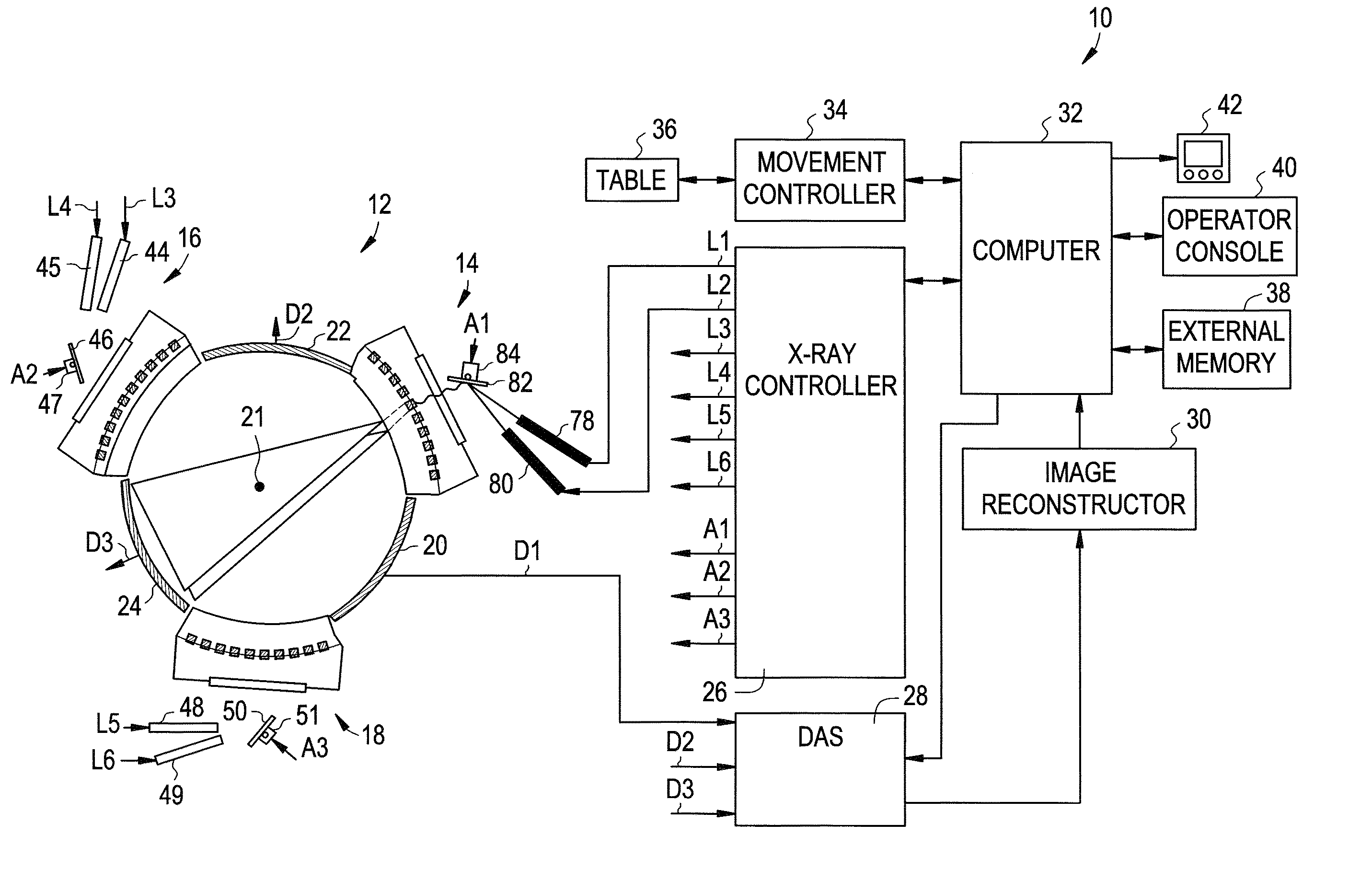
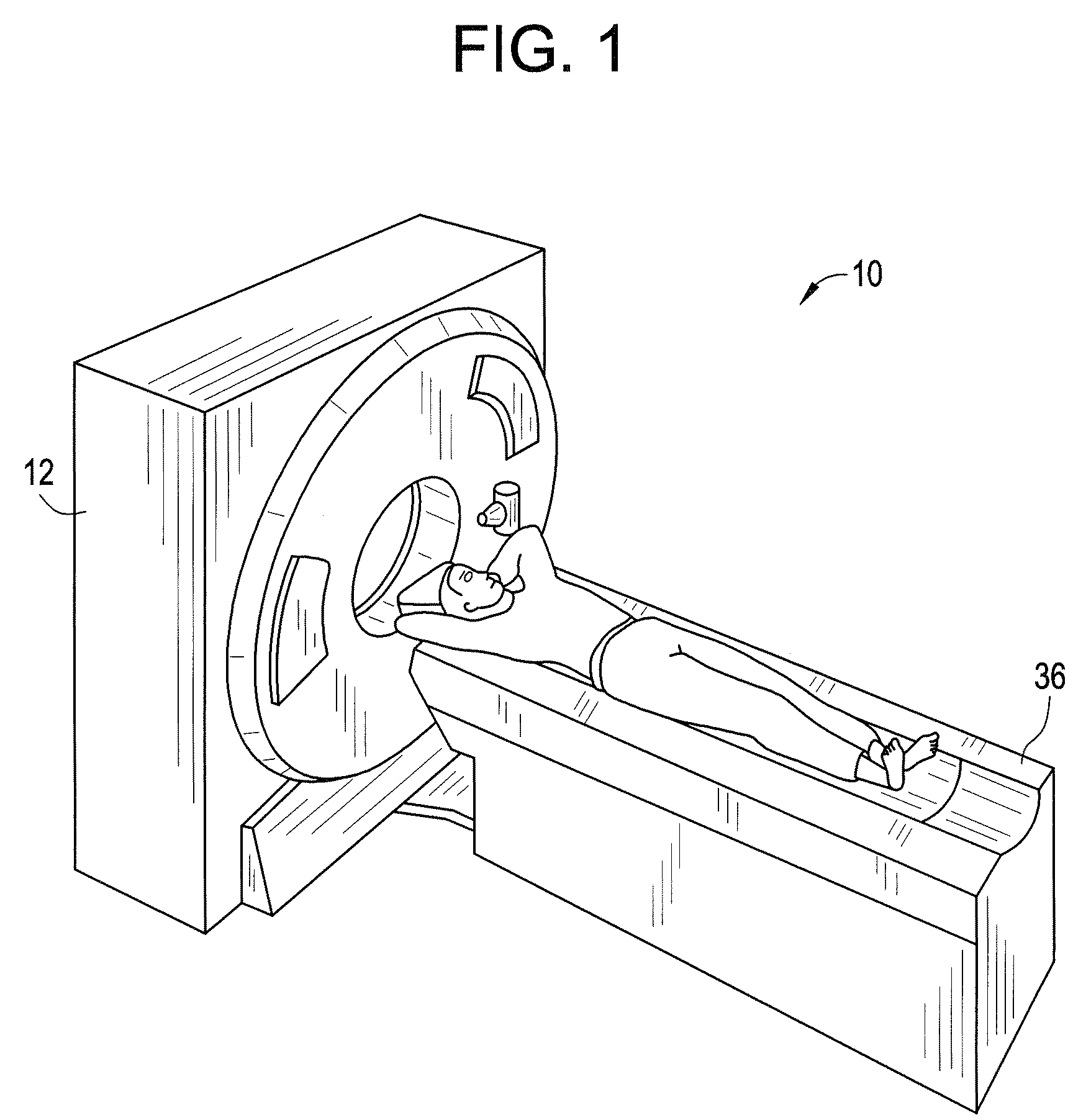
[0017]Referring to FIGS. 1 and 2, a CT imaging system 10 for generating digital images of a target object in accordance with an exemplary embodiment is shown. The CT imaging system 10 includes a CT scanner 12 including x-ray source subassemblies 14, 16, 18 and x-ray detector arrays 20, 22, 24, an x-ray controller 26, a data acquisition system 28, an image reconstructor 30, a computer 32, a movement controller 34, a table 36, an external memory 38, an operator console 40, and a computer monitor 42. It should be noted that in an alternate embodiment, CT imaging system 10 can have more than or less than three x-ray source subassemblies. Further, CT imaging system 10 can have more than or less than three x-ray detector arrays.

[0018]The CT scanner 12 is provided to generate a plurality of digital images of a target object. The CT scanner 12 includes the x-ray source subassemblies 14, 16, 18 and the x-ray detector arrays 20, 22, 24. Each x-ray source subassembly includes an x-ray detector...


PUM


Abstract

An electron emitter assembly and a method for generating electron beams are provided. The electron emitter assembly includes a light source configured to emit light. The electron emitter assembly further includes a photo-responsive device operably coupled to an electron emitter device. The photo-responsive device induces the electron emitter device to emit electrons in response to receiving the light. Finally, the electron emitter assembly includes an anode receiving the emitted electrons from the electron emitter device.

Description

BACKGROUND OF INVENTION[0001]X-ray devices have utilized electron emitter devices, such as field emitter arrays, to generate x-rays. Each field emitter array is coupled to an electrical control line that extends through the vacuum enclosure wherein a voltage signal applied over the control line induces the field emitter array to emit electrons. The emitted electrons are thereafter utilized to generate x-rays. Accordingly, because the x-ray device can utilize thousands of field emitter arrays having thousands of electrical control lines, a problem exists in routing the electrical control lines through apertures in a wall of the vacuum enclosure and providing a vacuum seal around each control line.[0002]Thus, there is a need for an electron emitter assembly that eliminates the need for routing electrical control lines through a wall of a vacuum enclosure to provide signals for inducing electron emitter assembly to emit electrons.BRIEF DESCRIPTION OF THE INVENTION[0003]An electron emit...

Claims


Application Information

Patent Timeline
Patent Type & Authority Patents(United States)
IPC IPC(8): H01J35/00
CPCA61B6/032A61B6/4014A61B6/4028H05G1/56H01J35/065H01J1/30H01J2235/068
Inventor DUNHAM, BRUCE MATTHEW
Owner GENERAL ELECTRIC CO
Why Eureka
Try Eureka