Automatic fingerprint identification method

a fingerprint identification and automatic technology, applied in the field of automatic fingerprint identification methods, can solve the problems of fingerprints, fingerprints, especially those recorded in connection with crime investigations, being smudged and broken, and fingerprints with erroneous features

Inactive Publication Date: 2006-08-01
RPX CORP
View PDF10 Cites 12 Cited by
  • Summary
  • Abstract
  • Description
  • Claims
  • Application Information

AI Technical Summary

Benefits of technology

[0007]An object of this invention is to provide a novel fingerprint identification method by means of which one-to-one identification of a person can be accomplished reliably in apparatus with limited computing capacity.
[0013]An advantage of the identification method according to the invention is that it does not require complicated transformation and computation algorithms, whereby it can be utilized in an apparatus with a limited computing and memory capacity.

Problems solved by technology

However, in spite of its simplicity it is at the same time complicated to apply. FIG. 1a shows a fingerprint as it has been recorded.
Fingerprints, especially those recorded in connection with crime investigations, may be smudgy and broken, sometimes very much so.
Moreover, there are always some erroneous features in a fingerprint that do not belong to the true fingerprint.
However, erroneous features that appear in the fingerprint make identification more difficult.
However, the analysis and removal of errors require significant computing capacity.
Therefore, fingerprint-based automatic identification can be problematic in a portable apparatus with modest processing and memory capacity.

Method used


Image

  • Automatic fingerprint identification method
  • Automatic fingerprint identification method
  • Automatic fingerprint identification method

Examples


Embodiment Construction

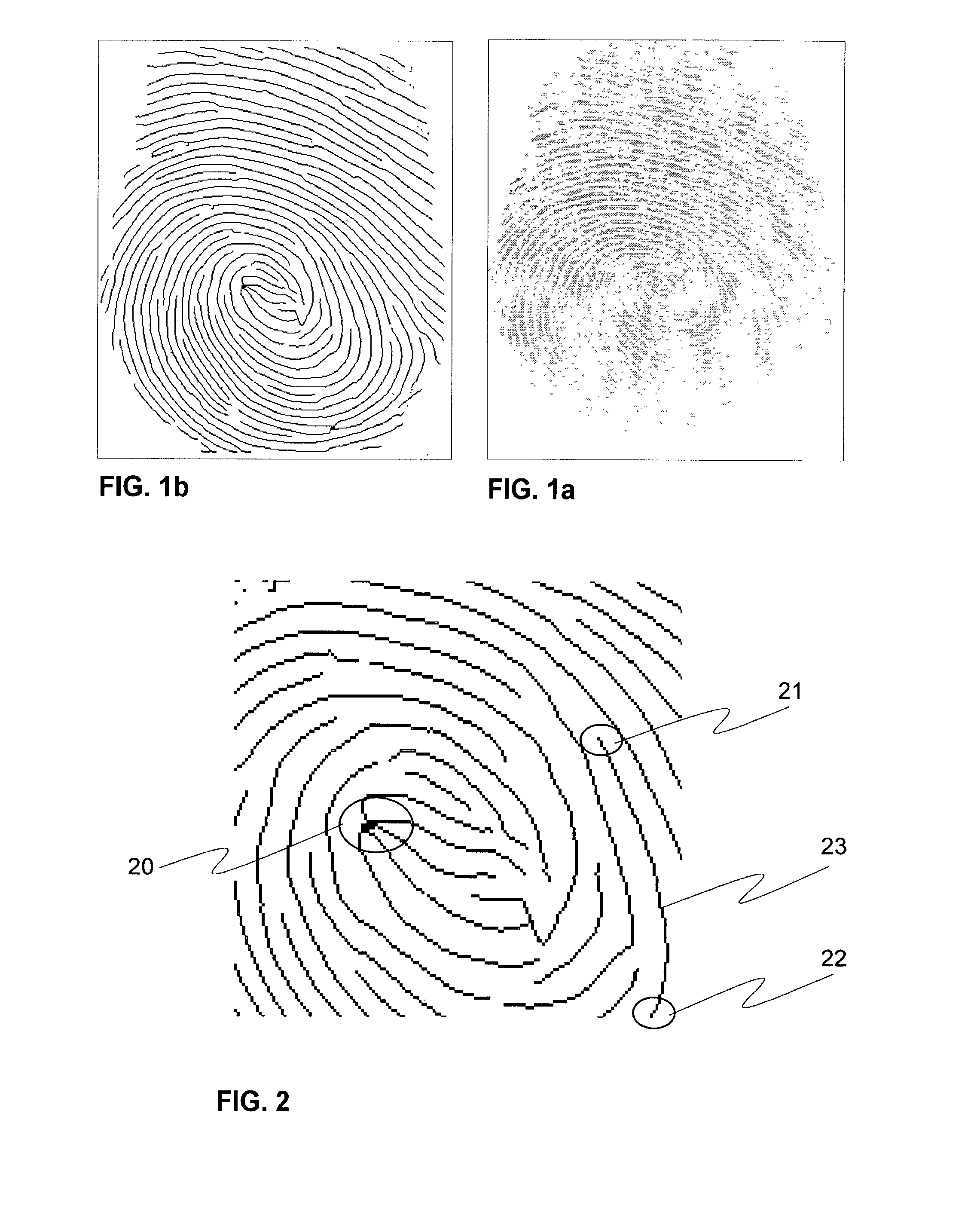
[0024]FIGS. 1a, 1b and 2 were already discussed in connection with the description of the prior art.

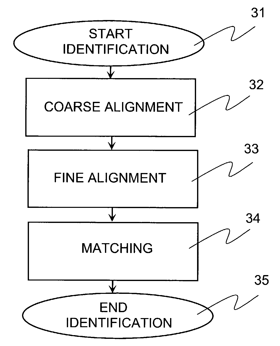
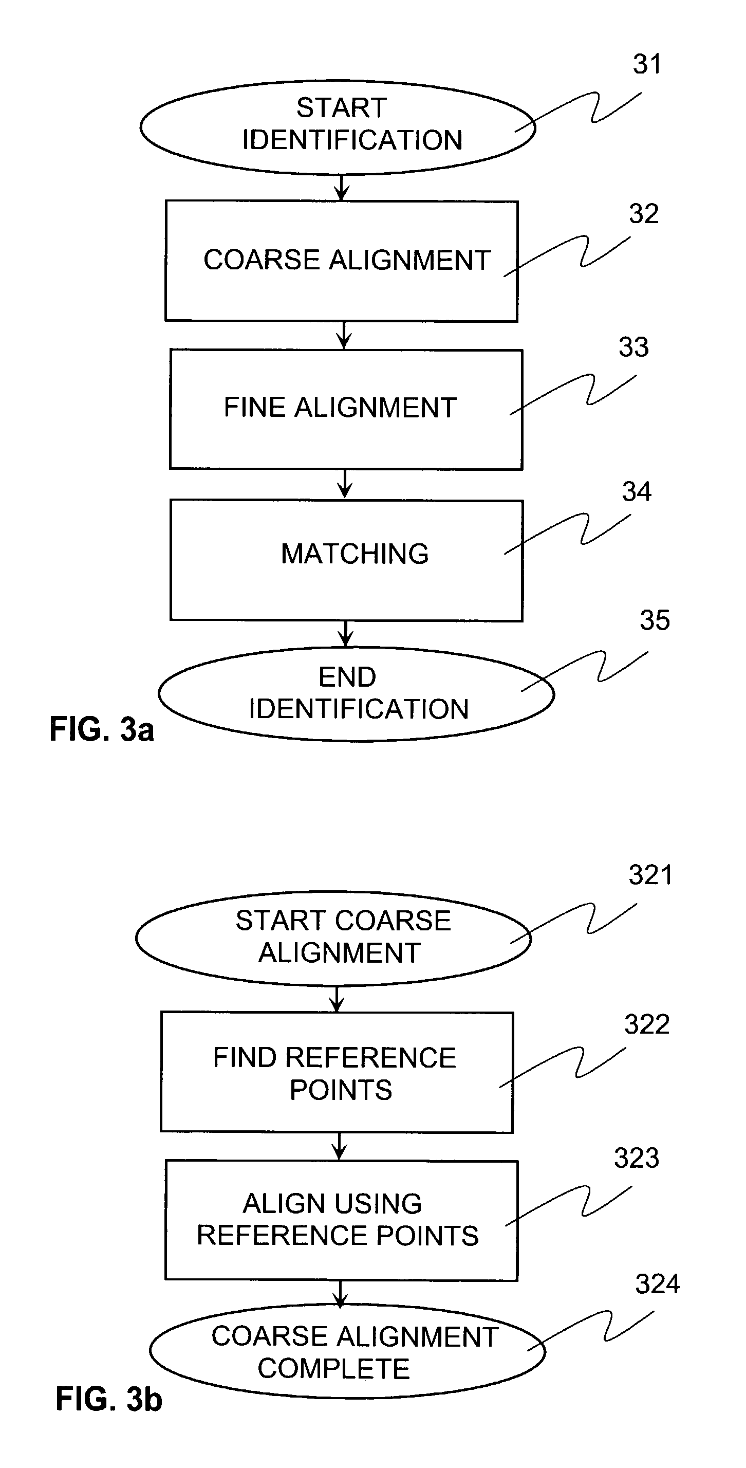
[0025]FIG. 3a shows as an example a flow diagram of the three main phases of the method according to the invention. The figure depicts a situation involving an automatic one-to-one identification, i.e. verification of a person's identity. The fingerprint identification process proper starts at step 31. Step 32 involves coarse alignment of the fingerprint to be identified and a template of a certain person's fingerprint stored in memory. The fingerprint to be identified is translated in such a manner that the fingerprints compared can be aligned using a few (4 to 5) “reference points” found in the fingerprint.

[0026]Fine alignment 33 involves the use of ridges 23, bifurcations 20 and endings 21, 22 found in the fingerprints. In this phase, the method attempts to match several compatible-looking minutiae. During each individual matching attempt it is possible to employ translation and ro...


PUM


Abstract

The invention relates to an automatic fingerprint identification method. In the method according to the invention, identification is executed in three phases. In coarse alignment (32), fingerprints are compared using a few reference points. In fine alignment (33), coincidence of fingerprint minutiae are used to find the best fingerprint matching transformation. In the matching phase (34), individual minutiae of the fingerprint examined are matched against a known template. Parameters are computed from the matching minutiae and used in making the final identification.

Description

FIELD OF THE INVENTION[0001]The invention relates to an automatic fingerprint identification method in which the fingerprint to be identified is matched against a template in memory. The invention further relates to a terminal employing the method.BACKGROUND OF THE INVENTION[0002]The need to identify people is ancient. Perhaps the oldest known identification method is the one based on a fingerprint of a person. Already thousands of years B.C.E. various documents were authenticated by making an impression of a finger on a seal. In the early 1900's, crime investigators begun utilizing fingerprints in their work because by that time it had been ascertained that fingerprints were unique to each person and that they do not change during the lifetime of a person. Special fingerprint matching equipment were developed in the 20th century to optically compare fingerprints and look for matches in existing databases.[0003]Reliable automatic identification of individuals is a growing problem. M...

Claims


Application Information

Patent Timeline
Patent Type & Authority Patents(United States)
IPC IPC(8): G06K9/00G06T7/00G06K9/64G07C9/00
CPCG06K9/00087G07C9/00087G06K9/6206G07C9/257G06V40/1365G06V10/754
Inventor AILISTO, HEIKKILINDHOLM, MIKKO
Owner RPX CORP
Why Eureka
Try Eureka