
Driving device, position controller provided with driving device, and camera provided with position controller

Inactive Publication Date: 2006-08-01
MINOLTA CO LTD
View PDF13 Cites 30 Cited by
  • Summary
  • Abstract
  • Description
  • Claims
  • Application Information

AI Technical Summary

Benefits of technology

[0009]It is another object of the present invention to provide a driving device for an ultrasonic actuator which can perform a position servo control.

Problems solved by technology

However, the driving device disclosed in this publication controls the frequency while detecting a phase difference so that a disk-shaped ultrasonic motor can be constantly driven at a mechanical resonance frequency and is not intended to control the position of a vibrating body which corresponds to the movable member.
Nor is this system for controlling the position using a resonant state.

Method used


Image

  • Driving device, position controller provided with driving device, and camera provided with position controller
  • Driving device, position controller provided with driving device, and camera provided with position controller
  • Driving device, position controller provided with driving device, and camera provided with position controller

Examples


Embodiment Construction

[0029]Hereinafter, embodiments of the present invention are described with reference to the accompanying drawings. It should be noted that no description is given on the same construction by identifying it by the same reference numerals in the respective drawings.

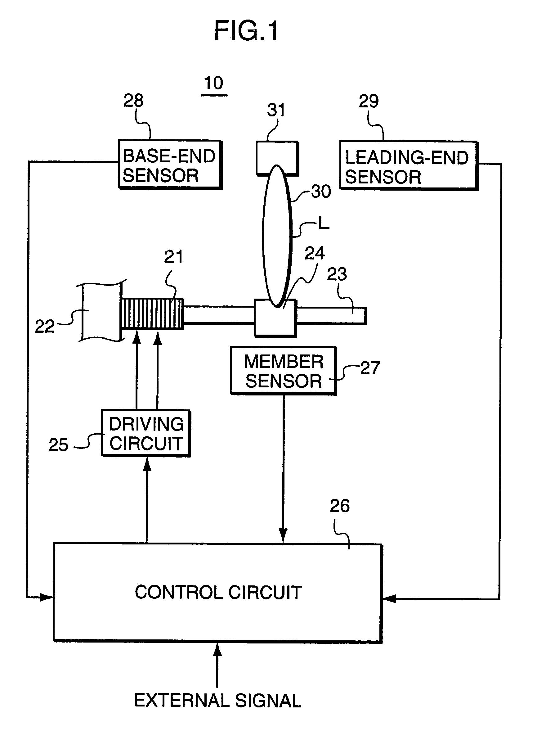
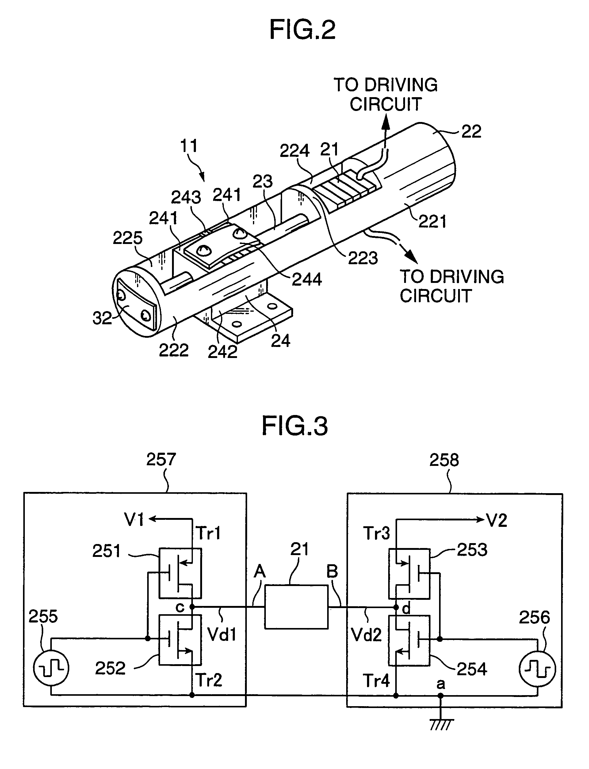
[0030]Referring to FIGS. 1 and 2 showing a construction of a driving device according to an embodiment is described, a driving device 10 is provided with an electromechanical conversion element 21, a supporting member 22, a driving member 23, a movable member 24, a driving circuit 25, a control circuit 26, a member sensor 27, a base-end sensor 28 and a leading-end sensor 29. An impact-type piezoelectric actuator 11 includes the electromechanical conversion element 21, the supporting member 22, the driving member 23 and the movable member 24.

[0031]The supporting member 22 is a part for holding the electromechanical conversion element 21 and the driving member 23 and is formed with first and second accommodating spaces 224, 2...


PUM


Abstract

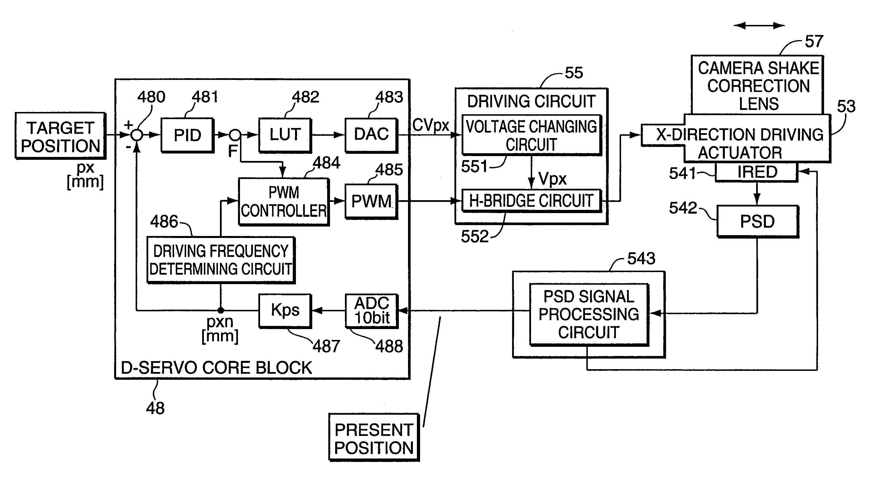
A driving device for an ultrasonic actuator for driving a movable member is provided with a member sensor for detecting a present position of the movable member, a calculator for calculating a control target position of the movable member, a driving circuit for generating such a drive voltage as to drive the ultrasonic actuator in a specified resonant state, and a control circuit for controlling an operative state of the movable member by adjusting at least one of physical quantities specifying the drive voltage as a maneuverable physical quantity in accordance with a difference between the present position and the control target position so that the movable member pursues the control target position. There can be provided a driving device capable of executing a position servo control while being driven in a specified resonant state, and a position controller and a camera provided with such a driving device.

Description

[0001]This application is based on patent application No. 2002-208854 filed in Japan, the contents of which are hereby incorporated by references.BACKGROUND OF THE INVENTION[0002]This invention relates to a driving device for an ultrasonic actuator, particularly to a driving device capable of a position servo control in an ultrasonic actuator driven in a specified resonant state, and also relates to a position controller provided with a driving device, and a camera provided with a position controller.[0003]In recent years, cameras such as still cameras, digital cameras and camera-integrated VTRs have been required to be smaller and more power-saving for portability and mobility. Thus, driving devices for driving focusing lenses, zoom lenses and camera shake correction lenses have been required to be smaller and more power-saving. Ultrasonic actuators using electromechanical conversion elements have been studied and developed for the use in driving devices to meet this request.[0004]...

Claims


Application Information

Patent Timeline
IPC IPC(8): G03B17/00H01L41/04G03B5/00G02B7/08H01L41/09H02N2/00
CPCG02B7/08H02N2/067H02N2/062H02N2/025
Inventor HARA, YOSHIHIRO
Owner MINOLTA CO LTD
Learn More