Ultrasonic actuator device and applications thereof

Active Publication Date: 2016-06-23
MAX PLANCK GESELLSCHAFT ZUR FOERDERUNG DER WISSENSCHAFTEN EV
View PDF0 Cites 7 Cited by
  • Summary
  • Abstract
  • Description
  • Claims
  • Application Information

AI Technical Summary

Benefits of technology

[0048]According to a particularly preferred embodiment of the invention, the ultrasonic driver device comprises at least two oscillator transducers having different resonance frequencies and being electrically connected in parallel with the power source. Advantageously, the parallel connection of the oscillator transducers allows the provision of only one wire connection (typically two lines) for powering and controlling all oscillator transducers simultaneously. Each of the oscillator transducers can

Problems solved by technology

Currently, miniaturization of micro machinery is hindered by the size of the available actuators and the control and electronics that is needed to operate them.
Electromagnetic motors, which work at larger scales (with diameters larger than about a centimeter), are difficult to miniaturize to below one millimeter.
However, a drawback common to all of these actuators is that they are all connected to complex wire connections or tubes to provide the power and to control the actuation.
This problem limits the application of these actuators, and means that their overall size is also bigger.
Actuators for multiple degrees-of-freedom require an increasing number of wires (or tubes) as the degree-of-freedom increases, as besides the power additional control cables are needed, which dramatically increases the complexity and rigidity of the connections, and eventually causes operational problems if the device is too small.
However, these approaches convert mechanical vibration to electricity using the piezoelectric effect and then utilize the electricity to power a device.
This electricity conversion

Method used


Image

  • Ultrasonic actuator device and applications thereof
  • Ultrasonic actuator device and applications thereof
  • Ultrasonic actuator device and applications thereof

Examples


Embodiment Construction

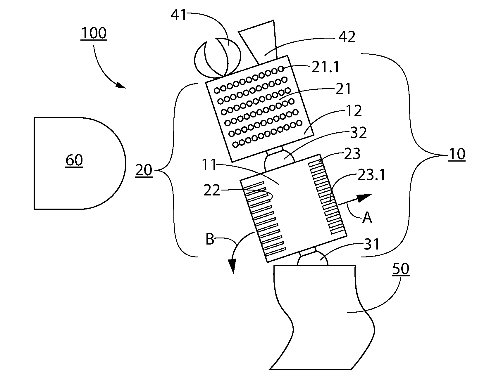
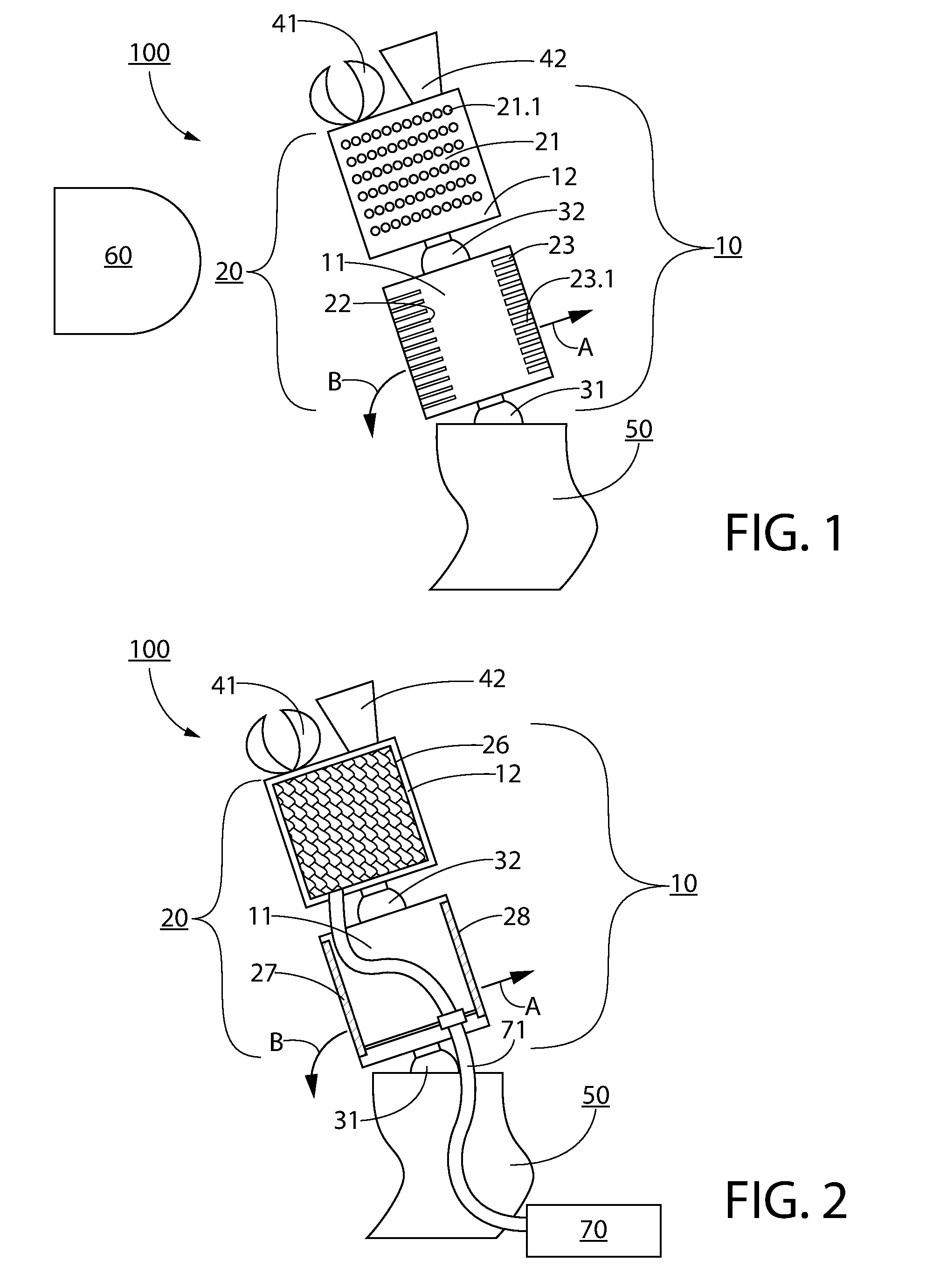
[0064]In the following, exemplary reference is made to endoscope applications of an inventive ultrasonic actuator device. The endoscope for in vivo diagnostics is a possible application of the ultrasonic streaming wireless or wire-bound actuator of the invention. On the one hand, a medical device in vivo requires a small size and simple access to power; on the other hand, ultrasound is already used in many medical procedures, including imaging, the break-up of (kidney) stones, tissue ablation etc.. Ultrasound has been shown to penetrate the human body and to be safe if the exposed power is appropriately controlled. It is emphasized that the invention is not restricted to the endoscopy example, but rather can be used also e.g. with other medical devices, like a biomedical device for minimally invasive surgery and / or a catheter, or with measuring devices or robot arms of mechanical machines, e.g. a robot arm for use in water, e.g. outside a submarine vehicle.

[0065]Embodiments of the i...


PUM


Abstract

Ultrasonic actuator device (100) includes actuator arm arrangement (10) including first and second actuator sections (11,12), wherein the first section is arranged for coupling with support structure (50) and the second section is movable relative to the first section, and ultrasonic driver device (20) including at least one ultrasonic driver unit (21-28) coupled with at least one of first and second sections for driving actuator arm arrangement (10) and for providing movement of the second section relative to the first section, and wherein actuator arm arrangement (10) is movable with at least two degrees of freedom and the at least one ultrasonic driver unit includes an array of oscillating elements being arranged for creating an acoustic stream in an adjacent medium in response to application of ultrasound. Furthermore, an operational instrument including at least one ultrasonic actuator device (100) and a method of using the device are described.

Description

BACKGROUND OF THE INVENTION[0001]The invention relates to an ultrasonic actuator device, comprising in particular a movable actuator arm arrangement and at least one ultrasonic driver unit, which is arranged for driving the actuator arm arrangement by acoustic streaming. Furthermore, the invention relates to an operational instrument, e. g. a medical instrument, like an endoscope, a biomedical device for minimally invasive surgery, and / or a catheter, or a mechanical machine apparatus, comprising at least one ultrasonic actuator device. Furthermore, the invention relates to methods of using the ultrasonic actuator device. Applications of the invention are available e.g. in the fields of miniaturized actuators, micro actuators, wireless machines, measuring devices, and medical endoscope technology. Further applications include wireless control of tools and machinery.[0002]For describing the background of the invention, particular reference is made to the following publications:[0003][...

Claims


Application Information

Patent Timeline
IPC IPC(8): H02N2/10A61B17/00
CPCH02N2/108A61B2017/00398A61B17/00H02N2/103F03G7/002A61B2017/003A61B2017/00345A61B2017/00402A61B2017/00407A61B2017/00411A61B2017/00415A61B17/29A61B34/30A61B90/361A61B1/05A61B1/00183A61B34/72
Inventor QIU, TIANFISCHER, PEER
Owner MAX PLANCK GESELLSCHAFT ZUR FOERDERUNG DER WISSENSCHAFTEN EV
Why Eureka
Try Eureka