Ultrasonic-actuator driving apparatus and ultrasonic-actuator driving method

A technology of a driving device and a driving method, which can be applied to the parts of piezoelectric devices or electrostrictive devices, piezoelectric effect/electrostrictive or magnetostrictive motors, device parts, etc., can solve the position stop accuracy Deterioration, deviation of moving state, high retention force, etc.

Inactive Publication Date: 2004-12-01
OLYMPUS CORP
View PDF1 Cites 6 Cited by
  • Summary
  • Abstract
  • Description
  • Claims
  • Application Information

AI Technical Summary

Problems solved by technology

[0004] (2) Strong holding force
[0013] However, in general, in ultrasonic actuators, the resonant frequency of the vibrator may suddenly change due to self-heating or external factors, or the movement state may deviate even if a certain driving frequency is applied. unstable factor
[0014] However, in the prior art disclosed in the aforementioned U.S. Patent No.

Method used


Image

  • Ultrasonic-actuator driving apparatus and ultrasonic-actuator driving method
  • Ultrasonic-actuator driving apparatus and ultrasonic-actuator driving method
  • Ultrasonic-actuator driving apparatus and ultrasonic-actuator driving method

Examples


no. 1 example

[0031] [structure]

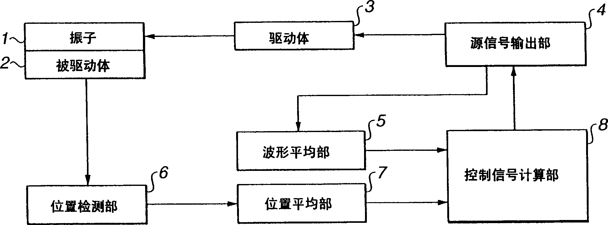
[0032] figure 1 Showing the first embodiment of the ultrasonic actuator driving device of the present invention, it is a block diagram showing the overall structure of the device.

[0033] Ultrasonic actuator driving device of the present invention such as figure 1 As shown, its structure includes: the vibrator 1 and the driven body 2 constituting the ultrasonic actuator, the driving part 3, the source signal output part 4, the waveform averaging part 5, the position detecting part 6, the position averaging part 7 and the control signal calculation part 8.

[0034] To further describe, an ultrasonic actuator is provided in which a driven body 2 in contact with a vibrator 1 is frictionally driven; and a drive unit 3 is electrically connected to the vibrator 1 of the ultrasonic actuator. The drive unit 3 applies a cyclic voltage to the vibrator 1 .

[0035] The active signal output unit 4 is electrically connected to the drive unit 3 . The source signal...

no. 2 example

[0050] [structure]

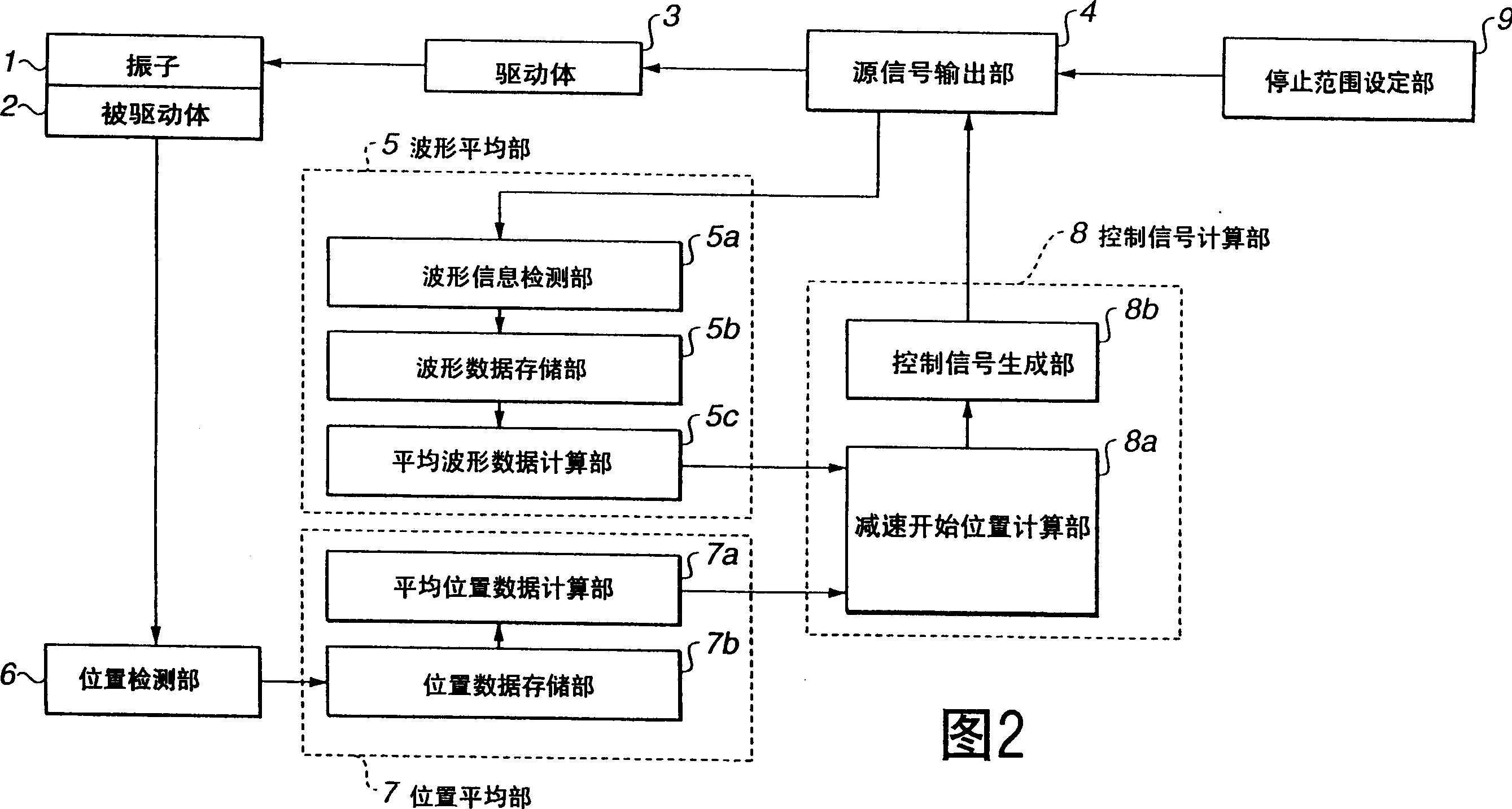
[0051] Fig. 2 shows a second embodiment of the ultrasonic actuator driving device of the present invention, and is a block diagram showing the overall structure of the device. In addition, in FIG. 2, the same symbols are attached to the same constituent elements as those of the apparatus of the first embodiment described above, and description thereof will be omitted, and only different parts will be described.

[0052] In the ultrasonic actuator driving device of this embodiment, the difference from the above-mentioned first embodiment is that, in order to realize driving control for higher precision and stable positioning, the waveform averaging unit 5 and the position averaging unit are configured in more detail. 7 and the control signal calculation part 8, and a stop range setting part is set.

[0053] As shown in FIG. 2 , the waveform average unit 5 includes a waveform information detection unit 5 a, a waveform data storage unit 5 b, and an average w...

no. 3 example

[0082] [structure]

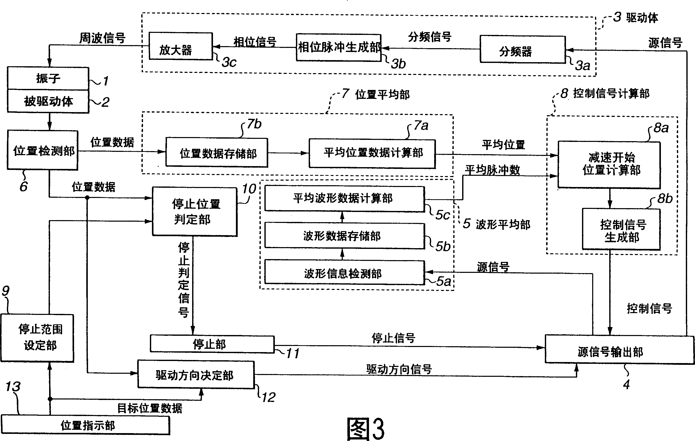
[0083] Figure 3 and Figure 4A to Figure 4C A third embodiment of the ultrasonic actuator driving device of the present invention is shown. Fig. 3 is a block diagram showing the overall structure of the device, Figure 4A to Figure 4C is a flow chart for explaining the ultrasonic actuator driving method of the present invention applied to the device, Figure 4A is the main initial setting processing routine, and Fig. 4B is the control process processing routine, Figure 4C Yes indicates that the process processing routine is stopped. Furthermore, in FIG. 3 , the same structures as those of the apparatuses of the first and second embodiments above are denoted by the same symbols, their descriptions are omitted, and only the different parts are described.

[0084] The ultrasonic actuator driving device of this embodiment is characterized in that, in order to realize drive control for high-precision and stable positioning, on the basis of the components o...


PUM


Abstract

An ultrasonic-actuator driving apparatus includes an ultrasonic actuator including a transducer and a driven body that is in contact with the transducer, the transducer to which a frequency signal is applied friction-driving the driven body; an original-signal outputting unit for outputting an original signal; a waveform averaging unit for averaging the original signals during a predetermined period to calculate average-waveform data; a position detecting unit for detecting an absolute position of the driven body with respect to the transducer; a position averaging unit for averaging the absolute positions during a predetermined period to calculate average-position data; a control-signal calculating unit that generates a control signal for controlling the frequency of the original signal based on the average-waveform data and the average-position data and supplies the control signal to the original-signal outputting unit; and a driving unit for generating the frequency signal based on the original signal and applying the frequency signal to the transducer.

Description

technical field [0001] The present invention relates to an ultrasonic actuator driving device and an ultrasonic actuator driving method, and in particular to an ultrasonic actuator that drives a driven body that is in contact with the above-mentioned vibrator by applying a cycle signal to the ultrasonic vibrator of the ultrasonic actuator. Device and ultrasonic actuator driving method. Background technique [0002] In recent years, ultrasonic motors (also called ultrasonic actuators) have attracted attention as a new type of motor replacing electromagnetic motors. Compared with the existing electromagnetic motor, the ultrasonic motor has the following advantages: [0003] (1) Low speed and high thrust can be obtained without gears. [0004] (2) Strong holding force. [0005] (3) Long stroke and high resolution. [0006] (4) Strong quietness. [0007] (5) It does not generate magnetic noise and is not affected by noise. [0008] In the ultrasonic motor driving device ha...

Claims


Application Information

Patent Timeline
IPC IPC(8): H02N2/00H01L41/04H02N2/14
CPCH02N2/0075
Inventor 葛西靖明
Owner OLYMPUS CORP
Why Eureka
Try Eureka