Blade tip clearance control

a technology of blade tip and clearance control, which is applied in the direction of engine components, pumps, non-positive displacement fluid engines, etc., can solve the problems of blade tip rubbing, difficult to ensure that adequate blade tip clearance is maintained, and blade tip clearance can actually decrease, so as to achieve the clearance between the blade tips

Active Publication Date: 2006-08-08
SIEMENS ENERGY INC
View PDF22 Cites 21 Cited by
  • Summary
  • Abstract
  • Description
  • Claims
  • Application Information

AI Technical Summary

Benefits of technology

[0009]In another respect, aspects of the invention relate to a turbine system. The system includes a turbine engine having a compressor section, a combustor section, and a turbine section. The turbine section includes a plurality of discs mounted to a rotor. A plurality of blades are attached to the discs. A stationary blade ring surrounds at least a portion of the blades. The system further includes a channel that extends from the combustor section to the blade ring. The channel permits flow of a portion of combustion gases out of the combustor section. The channel further includes an inlet for permitting entry of a portion of compressor exit air such that the compressor exit air can mix with the combustion gases in the channel so as to cool the combustion gases. Upon exposure to the mixed combustion gases and compressor exit air, the clearance between the tips of the blades and the surrounding stationary blade ring increases.
[0010]The system can further include a valve for regulating the flow of combustion gases into the channel. The valve can substantially restrict the flow of combustion gases through the channel when the engine reaches substantially steady state operation. Substantially steady state operation can include at least base load operation. The blade ring can include an outlet for discharging the mixture of combustion gases and compressor exit air downstream of the first row of blades and into the turbine gas flow.

Problems solved by technology

However, during transient conditions such as during engine startup or part load operation, it can be difficult to ensure that adequate blade tip clearances are maintained because the rotating parts (blades, rotor, and discs) and the stationary parts (outer casing, blade rings, and ring segments) thermally expand at different rates.
As a result, blade tip clearances can actually decrease during engine startup or part load operation, raising concerns of blade tip rubbing.

Method used


Image

  • Blade tip clearance control
  • Blade tip clearance control

Examples


Embodiment Construction

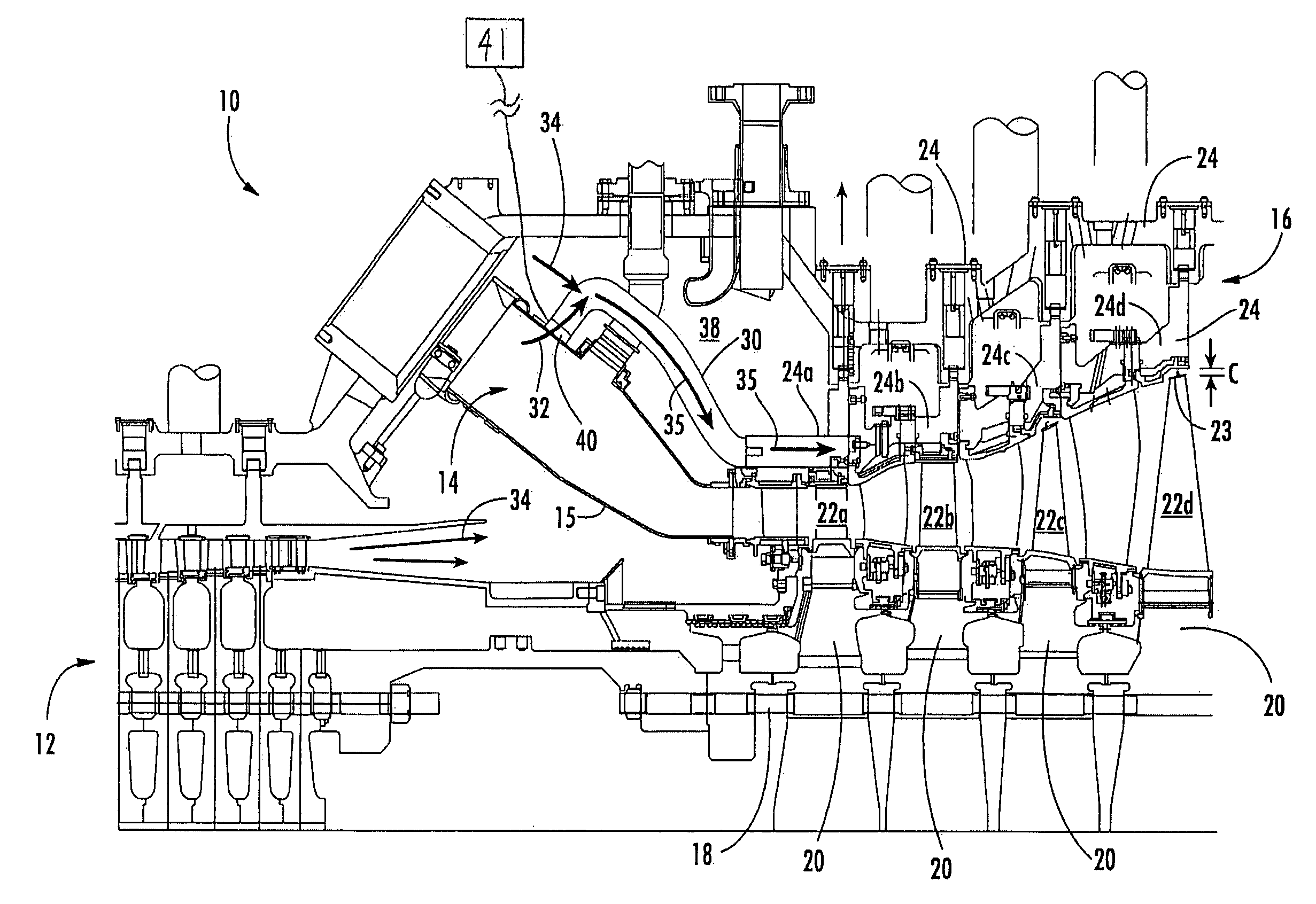
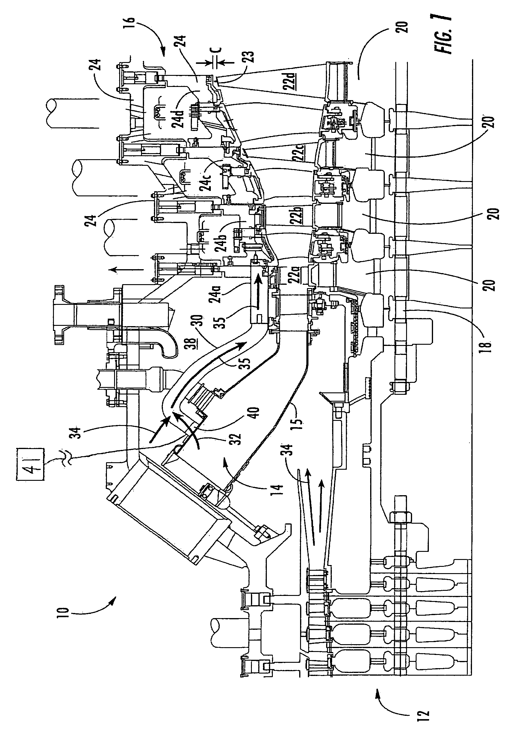
[0012]Aspects of the present invention relate to actively managing blade tip clearances while a turbine engine is operating under transient conditions such as at engine startup or during part load operation. Aspects of the invention are described in connection with a turbine engine system and a method of operation.

[0013]Embodiments according to aspects of the invention are shown in FIG. 1, but the present invention is not limited to the illustrated structure or application. Further, the following detailed description is intended only as exemplary.

[0014]Aspects of the invention can be applied to a variety of turbine engine systems. A turbine engine 10 can generally include a compressor section 12, a combustor section 14 and a turbine section 16. Each of these sections can have a variety of components and configurations as would be appreciated by one skilled in the art. For example, the combustor section 14, illustrated with a transition 15, contains hot combustion gases flowing to th...


PUM


Abstract

Aspects of the invention relate to a turbine engine system and method for actively managing blade tip clearances during part load operation of the engine. Aspects of the invention relate to extracting a portion of the combustion gases from the combustor section of the engine and routing these heated gases to the blade rings or other stationary structure surrounding the turbine blades. Upon exposure to the combustion gases, which can be mixed with compressor exit air, the stationary structure will thermally expand, causing blade tip clearances to increase. Thus, concerns of blade tip rubbing are minimized. Once the engines achieves steady state operation, the flow of the combustion gases to the blade rings can be substantially restricted so that only compressor exit air is supplied to the stationary structure. Consequently, the stationary structure will contract and the blade tip clearances will decrease, thereby increasing the efficiency of the turbine.

Description

FIELD OF THE INVENTION[0001]The invention relates in general to turbine engines and, more particularly, to optimizing blade tip clearances during startup and part load engine operation.BACKGROUND OF THE INVENTION[0002]The turbine section of a turbine engine can include a rotor with discs on which a plurality of blades are attached. The blades extend radially outward from the discs and terminate in a region known as the blade tip. The blades are surrounded by a stationary support structure of the turbine, which can include an outer casing and blade rings. The space between the tips of the rotating blades and the neighboring stationary structure is referred to as the blade tip clearance.[0003]For engine integrity, it is important that the tips of the blades do not rub against the nearby stationary structure. However, during transient conditions such as during engine startup or part load operation, it can be difficult to ensure that adequate blade tip clearances are maintained because ...

Claims


Application Information

Patent Timeline
Patent Type & Authority Patents(United States)
IPC IPC(8): F02C1/00F01D11/24
CPCF01D11/24
Inventor CHEHAB, ABDULLATIFLITTLE, DAVID A.
Owner SIEMENS ENERGY INC
Why Eureka
Try Eureka