Power transmission system and operation method therefor

a transmission system and power technology, applied in hybrid vehicles, gearing, electric propulsion mounting, etc., can solve the problems of increased maintenance costs, electric motors being forced to rotate, and electric motors being burdened with electric motors

Inactive Publication Date: 2006-08-08
TOCHIGI FUJI IND CO LTD
View PDF33 Cites 38 Cited by
  • Summary
  • Abstract
  • Description
  • Claims
  • Application Information

AI Technical Summary

Benefits of technology

[0018]The present invention is made with such points in view. It therefore is an object of the present invention to provide a power transmission system with a compact size, light weight, and well adaptation for vehicle-mounting, preventing an electric motor from being caused to rotate by rotation of wheels, and an operation method for the same.

Problems solved by technology

In the conventional electric automobiles, an electric motor is connected directly to wheels, and even in a case of interruption of power supply to the electric motor, such as when travelling by inertia, the electric motor is forced to rotate together with wheel rotation, with burdens on the electric motor.
For example, if the electric motor is a brush type like a DC motor, brushes receive a great influence on the durability, resulting in increased maintenance costs, such as by increase in number of services for brush replacement.
As the rotation is increased in speed by the reduction gear set, there is produced a greater emf, resulting in burdens, such as on a battery or alternator (not shown) or on circuit elements such as a regulator constituted as an integrated circuit, causing a reduced durability.

Method used


Image

  • Power transmission system and operation method therefor
  • Power transmission system and operation method therefor
  • Power transmission system and operation method therefor

Examples


first embodiment

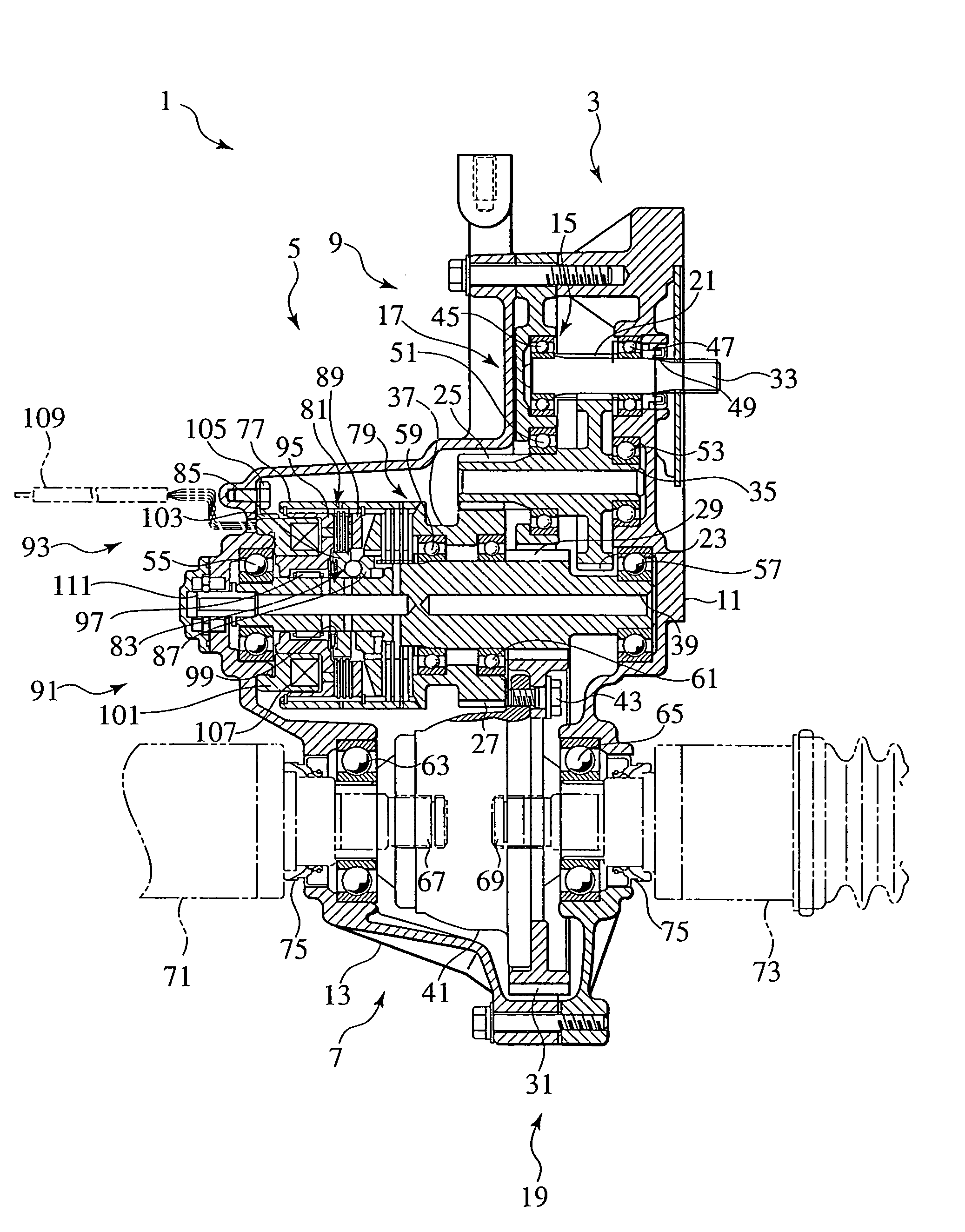
[0123]FIG. 1 and FIG. 2 show a transmission system 1 of drive power of an electric motor according to the first embodiment of the invention.

[0124]The power transmission system 1 has features of the 1st, 2nd, 6th, 7th, 8th, 12th, 13th, and 14th aspects of the invention. Note the terms “transverse”, “left” and “right” mean those of a vehicle equipped with the power transmission system 1, and those in FIG. 1.

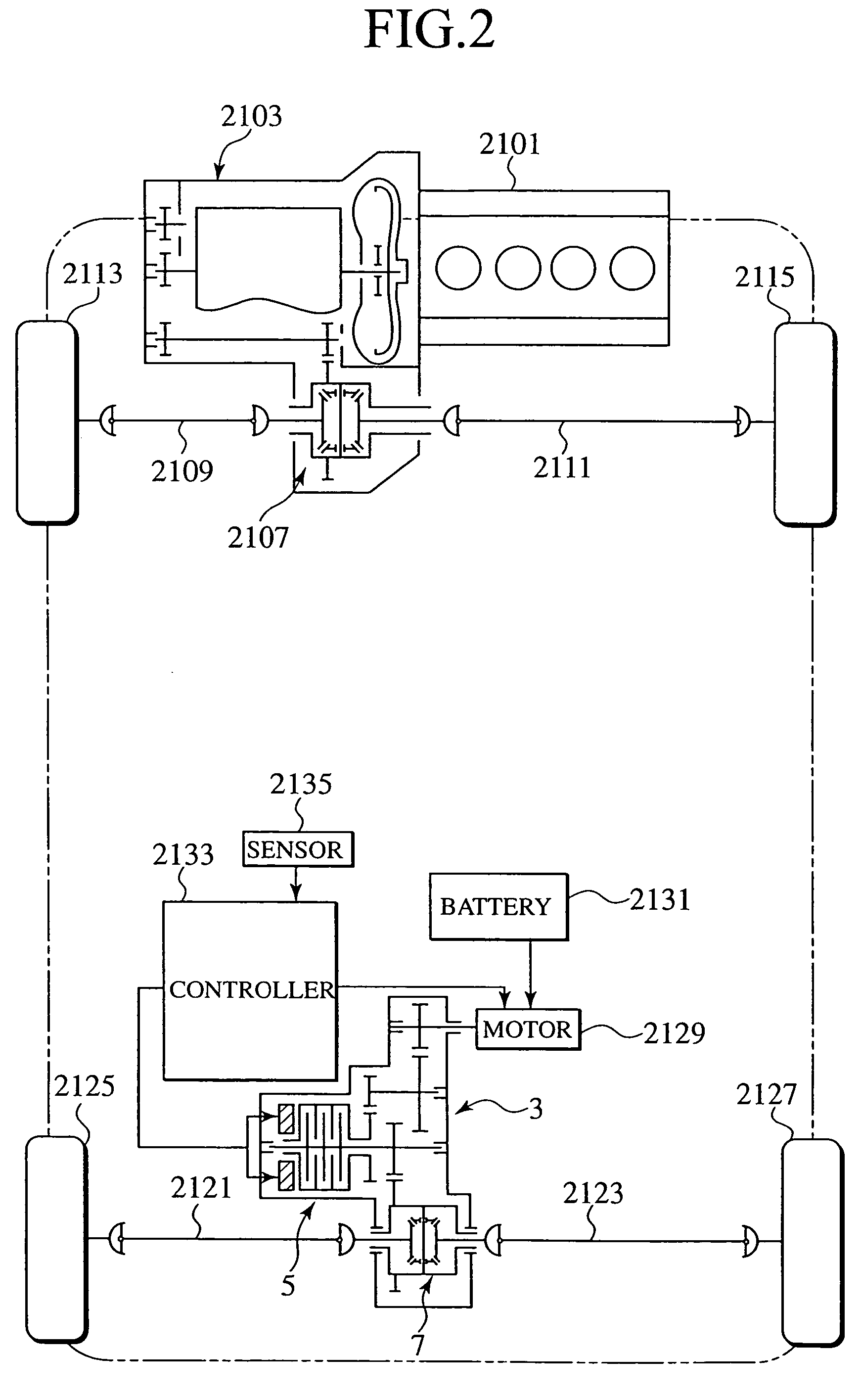
[0125]The power transmission system 1 is configured to be arranged on a rear wheel side of a four wheel driven vehicle using an engine and an electric motor, such as an electric automobile shown in FIG. 2, for example.

[0126]This vehicle is equipped with a power train system which has: a front-wheel side power train including a transversely arranged engine 2101, a transmission 2103, a front differential 2107 (as a differential apparatus for distributing drive power of the engine 2101 to left and right front wheels), left and right front axles 2109 and 2111, and left and right front ...

second embodiment

[0204]With reference to FIG. 3, description is made of a transmission system 201 of drive power of an electric motor 2129 according to the second embodiment of the invention and a method of operation thereof.

[0205]The power transmission system 201 has features of the 1st, 2nd, 8th, 9th, 10th, and 12th aspects of the invention. Note the terms “left” and “right” mean those of a vehicle equipped with the power transmission system 201, and those in FIG. 3.

[0206]Like reference numerals are given to members having like functions as those of the power transmission system 1 according to the 1st embodiment of the invention. Those members with like functions are not described to avoid redundancy.

[0207]The power transmission system 201 is constituted with a speed-reducing mechanism 203, an on-off clutch 205 (as a clutch) to be electromagnetically controlled, a rear differential 207 (as a differential apparatus), a controller 2133, etc.

[0208]The power transmission system 201 is accommodated in ...

third embodiment

[0244]With reference to FIGS. 4 and 5, description is made of a transmission system 301 of drive power of an electric motor 2129 according to the third embodiment of the invention and a method of operation thereof.

[0245]The power transmission system 301 has features of the 1st, 2nd, 8th, 9th, 13th, and 14th aspects of the invention and the operating method has features of the 18th and 19th aspects of the invention. Note the terms “left” and “right” mean those of a vehicle equipped with the power transmission system 301, and those in FIGS. 4 and 5. Like reference numerals are given to members having like functions as those of the power transmission systems 1 and 201 according to the 1st and 2nd embodiments of the invention. Those members with like functions are not described to avoid redundancy.

[0246]The power transmission system 301 is constituted with a speed-reducing mechanism 303, a rear differential 305 (as a differential apparatus), an on-off clutch 307 (as a clutch), a control...


PUM


Abstract

Between a speed reducing mechanism (15, 17, 19) for speed-reducing drive power of an electric motor and a differential apparatus (7) for distributing speed-reduced drive power to axle ends is disposed a clutch (5) configured for interruptive transmission of drive power.

Description

CROSS-REFERENCE TO RELATED APPLICATION[0001]This application is a division of application Ser. No. 09 / 829,335, filed on Apr. 9, 2001 now U.S. Pat. No. 6,770,005, which application is specifically incorporated herein, in its entirety, by reference.BACKGROUND OF THE INVENTION[0002]1. Field of the Invention[0003]The present invention relates to a power transmission system, such as for an electric automobile using an electric motor as a drive power source or an electric automobile using a fuel engine (an ordinary engine making use of an explosion of fuel) and an electric motor both as a drive power source, and to an operation method for the same.[0004]2. Description of the Related Art[0005]There is disclosed in Japanese Patent Application Laid-Open Publication No. 9-226394 a drive system 2001 for electric automobiles shown in FIG. 22.[0006]The drive system 2001 for electric automobiles includes an electric motor 2003, a reduction gear set 2005, and a differential apparatus 2007.[0007]Th...

Claims


Application Information

Patent Timeline
Patent Type & Authority Patents(United States)
IPC IPC(8): F16H3/72B60K1/00B60W10/02B60K6/20B60K6/365B60K6/38B60K6/383B60K6/387B60K6/40B60K6/405B60K6/442B60K6/48B60K6/52B60K6/54B60K6/547B60K17/02B60K17/04B60K17/16B60K17/356B60K23/08B60L50/16F16D28/00F16D48/06F16H48/06F16H48/08F16H48/20F16H48/295F16H48/32F16H48/34F16H48/38F16H48/40F16H57/023F16H57/031F16H57/037F16H57/038F16H57/039F16H57/04
CPCB60K1/00B60K6/383B60K6/387B60K6/40B60K6/405B60K6/442B60K6/48B60K6/52B60K6/54B60K6/547B60K17/02B60K17/04B60K17/356B60K23/08B60W10/02B60W10/08F16H57/04B60K6/365Y10T477/26B60K17/165B60L2240/423B60W20/00B60W2710/083F16H1/20F16H37/041F16H48/08F16H48/22F16H48/30Y02T10/6221Y02T10/6234Y02T10/6265Y10S903/903Y10S903/951Y10S903/946Y10S903/91Y10S903/914Y10S903/917Y10S903/916Y10S903/913Y10S903/952Y10S903/919Y10S903/912Y02T10/642Y02T10/7077Y10T477/23Y02T10/62Y02T10/64B60W20/10B60W10/30B60W10/10
Inventor AIKAWA, MASASHIYAMAZAKI, NOBUSHI
Owner TOCHIGI FUJI IND CO LTD
Why Eureka
Try Eureka