
Method and apparatus for an ambient energy battery or capacitor recharge system

a technology of ambient energy and capacitors, applied in electrical equipment, piezoelectric/electrostrictive/magnetostrictive devices, piezoelectric/electrostriction/magnetostriction machines, etc., to achieve the effect of maximimum useful energy

Inactive Publication Date: 2006-08-08
SAPURAST RES
View PDF24 Cites 74 Cited by
  • Summary
  • Abstract
  • Description
  • Claims
  • Application Information

AI Technical Summary

Benefits of technology

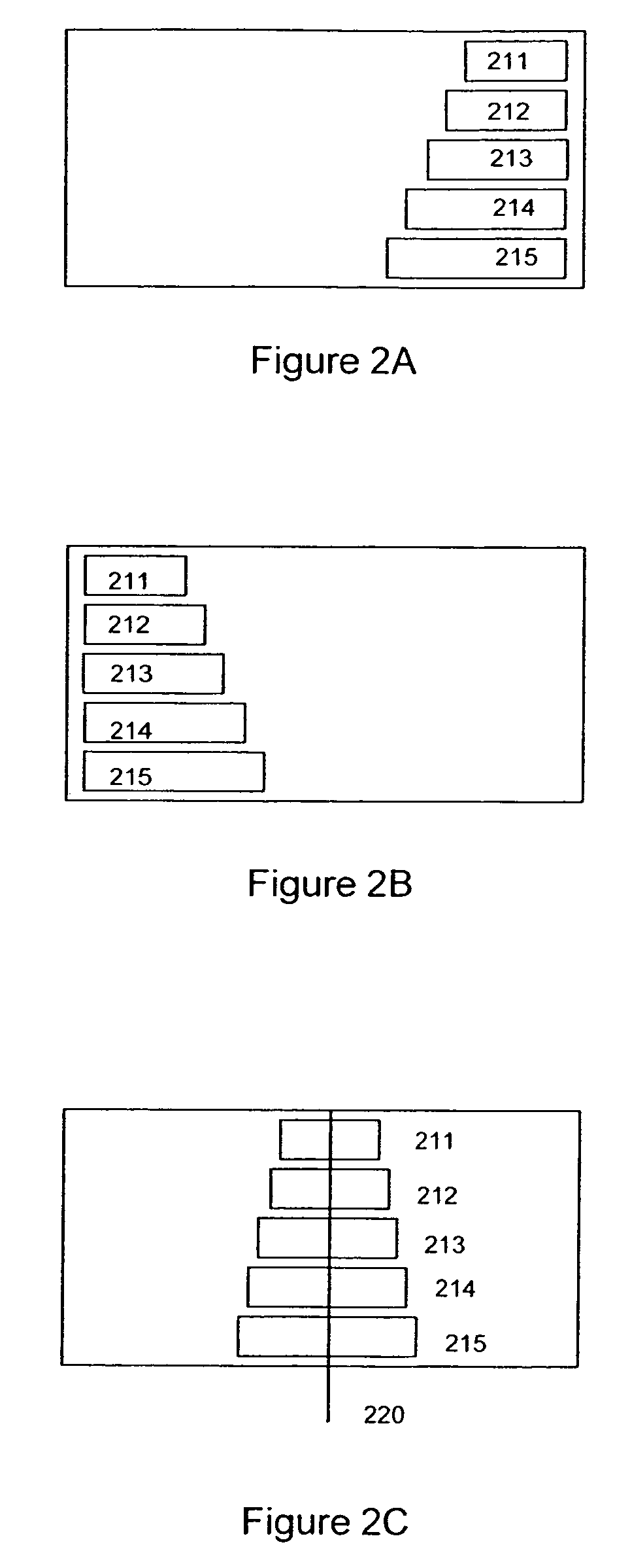
[0009]Another advantage of the present invention is that, in contrast to previous devices, the present invention preferably operates when supplied with even small amounts of energy such as longitudinal stretch motion relative to the object on which it is mounted. Furthermore, this stretch may supply energy even if it is limited to approximately 1.5 μm. Moreover, in temperature-based charging applications, the present invention may output pulses based on a significantly smaller temperature change due to the beneficial effect of charge stacking. In a stacked element array, the temperature change may be the same for all elements. Thus, to obtain the same voltage as with a prior charger that does not employ stacking, a change of 1° C. / the number of elements=the change in degrees Centigrade required to obtain an 8 volt output pulse. For example, in a five element stack, a 0.2° C. (one fifth degree Celsius) change may produce an approximate 8 volt open circuit output pulse.
[0010]An object of the present invention is to provide an ambient energy battery charging device that may be optimized for almost any environment. Another object of the present invention is to provide an ambient energy capacitor charging device that may be optimized for almost any environment.
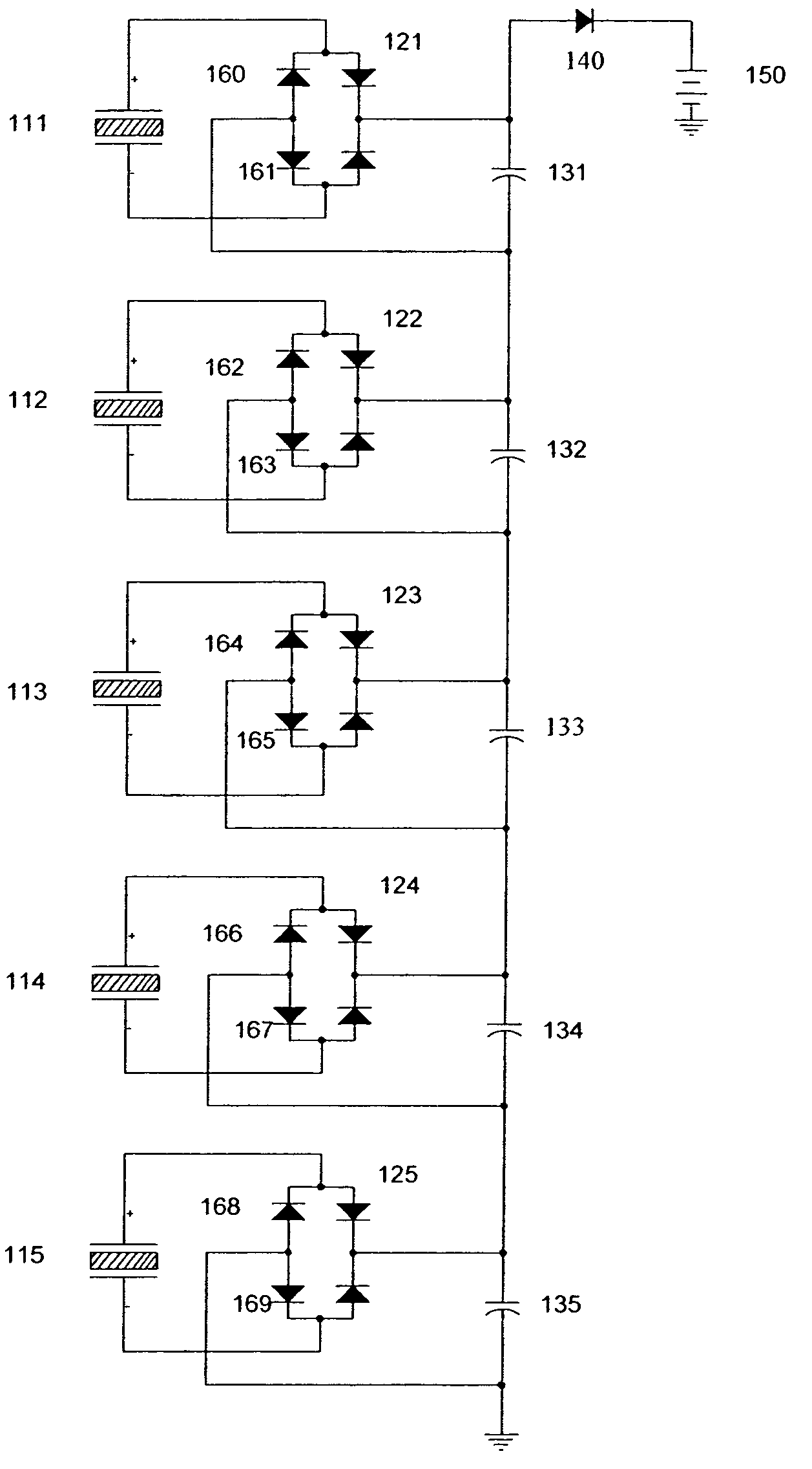
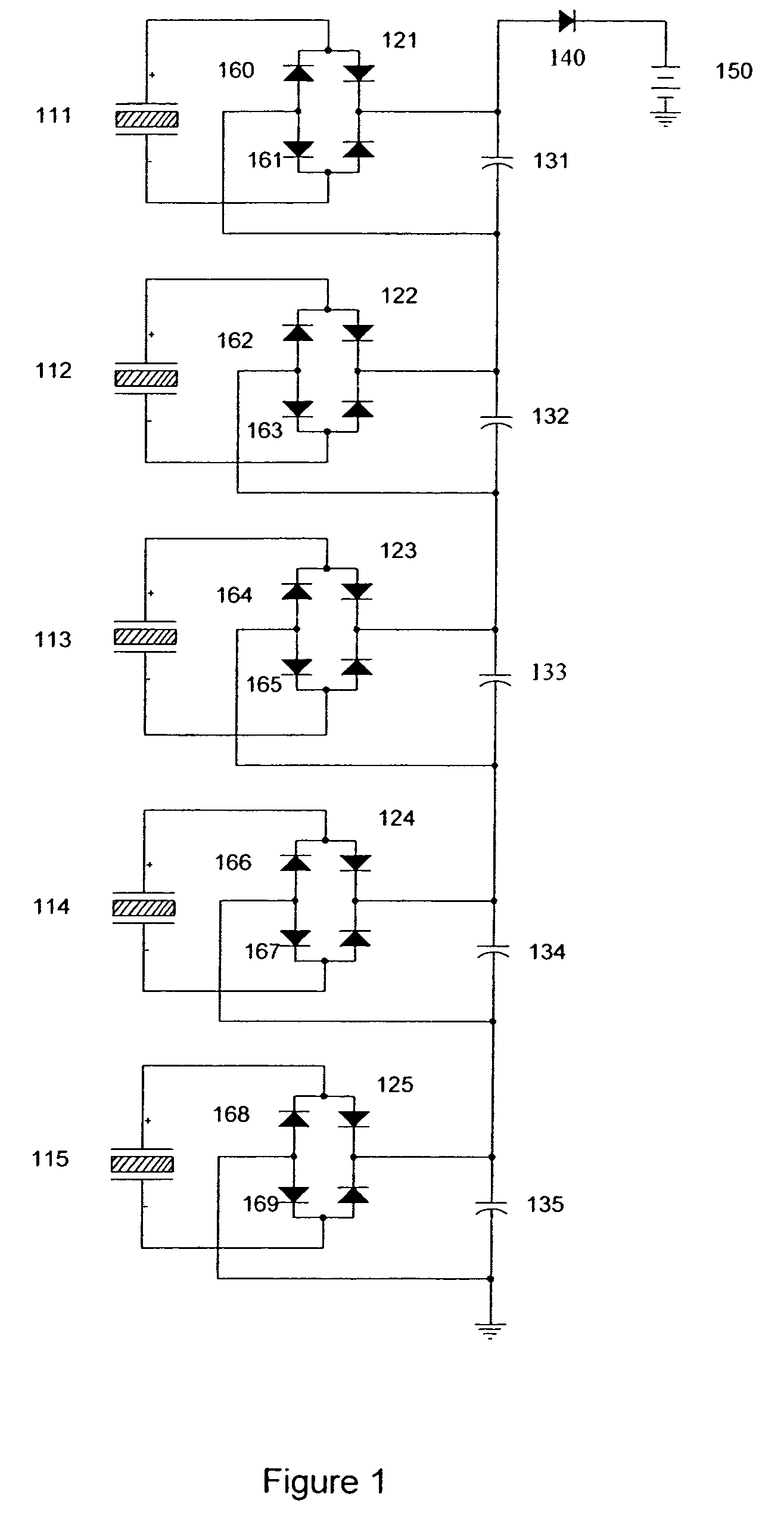
[0011]One embodiment of the present invention may be an apparatus for use as a charger utilizing ambient energy including a plurality of stacked piezoelectric elements, a rectification block on an output of each of the elements, a plurality of capacitors arranged to accumulate charge from the rectification blocks, and a blocking diode provided at an output of the plurality of capacitors. Moreover, in certain embodiments, a charge storage device may be connected to an output of the blocking diode.
[0012]In a particular embodiment of the present invention, the rectification block may be a full-wave rectification block or a half-wave rectification block. The apparatus may include five or more stacked piezoelectric elements. Moreover, in a further embodiment of the present invention, the apparatus may further include a signal phase delay element (such as, for example, an inductor) provided between the rectification blocks and the capacitors. In another particular embodiment of the present invention, the charge storage device may comprise a battery or capacitor.
[0013]The apparatus may be optimized for changes in ambient power from gravitational effects on a structure rotating at an angle to the surface of a significant gravity source. A wheel may be an example of such a structure. An appropriate angle to the surface may be approximately perpendicular, or approximately 90 degrees. Such an angle may provide the maximum amount of useful energy. In general, if other angles are used, the useful component will be the component perpendicular to the surface. Significant gravity sources may include the earth, the moon, or an asteroid.
[0014]The apparatus may be optimized for changes in ambient power from a human or other heartbeat. The apparatus may alternatively be optimized for changes in ambient power available from local electrical fields, particularly those on the approximate range of 50 to 60 Hz. In another embodiment, the apparatus may be optimized for changes in ambient power available from low power sound or ultrasound energy. In yet another embodiment, the apparatus may be optimized for changes in ambient power available from RF spectrum energy fields. In another embodiment, the apparatus may be optimized for changes in magnetic fields. Additionally, the apparatus may be optimized to capture very low frequency energy of any frequency down to the limit of the piezoelectric material. This limit is believed to be about 0.001 Hz for DT-1 material from Measurement Specialties Incorporated (Fairfield, N.J.).

Problems solved by technology

Furthermore, this stretch may supply energy even if it is limited to approximately 1.5 μm.

Method used


Image

  • Method and apparatus for an ambient energy battery or capacitor recharge system
  • Method and apparatus for an ambient energy battery or capacitor recharge system
  • Method and apparatus for an ambient energy battery or capacitor recharge system

Examples


Embodiment Construction

[0025]It is to be understood that the present invention is not limited to the particular methodology, compounds, materials, manufacturing techniques, uses, and applications described herein, as these may vary. It is also to be understood that the terminology used herein is used for the purpose of describing particular embodiments only, and is not intended to limit the scope of the present invention. It must be noted that as used herein and in the appended claims, the singular forms “a,”“an,” and “the” include the plural reference unless the context clearly dictates otherwise. Thus, for example, a reference to “an element” is a reference to one or more elements and includes equivalents thereof known to those skilled in the art. Similarly, for another example, a reference to “a step” or “a means” is a reference to one or more steps or means and may include sub-steps and subservient means. All conjunctions used are to be understood in the most inclusive sense possible. Thus, the word “...


PUM


Abstract

The present invention relates to the field of battery and capacitor charging. In particular, the present invention provides pulsed current charging using changes, regardless of polarity, in the local energy environment to obtain power. The present invention relates, for example, to ambient energy charging thin film batteries, other batteries, or capacitors, via, for example, polyvinyladine fluoride homopolymer (PVDF), PVDF bi-axially poled, or other piezoelectric materials. Ambient energy may be defined as any change in energy within the local environment. Charging can be accomplished with, and is not limited to, positive or negative changes of the following energy types: thermal; visible light, including infrared and ultraviolet; mechanical motion or impact; triboelectric, including airflow or physical contact; movement in relation to a gravitational plane (increase or decrease in gravitational potential energy); and radio frequency (RF) electromagnetic energy, regardless of specific frequency.

Description

CROSS REFERENCE TO RELATED APPLICATIONS[0001]The present application is related to and claims the benefit under 35 U.S.C. § 119(e) of U.S. Provisional Patent Application Ser. No. 60 / 464,357 filed 22 Apr. 2003, which is expressly incorporated fully herein by reference.FIELD OF THE INVENTION[0002]The present invention relates to the field of battery and capacitor charging. In particular, the present invention provides pulsed current charging using changes, regardless of polarity, in the local energy environment to obtain power. The present invention relates, for example, to ambient energy charging thin film batteries, other batteries, or capacitors, via, for example, polyvinyladine fluoride homopolymer (PVDF), PVDF bi-axially poled, or other piezoelectric materials. Ambient energy may be defined as any change in energy within the local environment. Charging can be accomplished with, and is not limited to, positive or negative changes of the following energy types: thermal; visible lig...

Claims


Application Information

Patent Timeline
Patent Type & Authority Patents(United States)
IPC IPC(8): H01L41/08H10N30/00H02N2/18H10N30/30
CPCH02N2/181
Inventor BRANTNER, PAULPEARCE, MICHAEL BAKERTRUJILLO, ADOLPH
Owner SAPURAST RES
Learn More